Electric connector for electric tool

A technology of electric tools and electrical connectors, applied in the direction of multi-purpose hand tools, connections, electrical components, etc.

Inactive Publication Date: 2003-06-04
BLACK & DECKER INC
View PDF1 Cites 14 Cited by
  • Summary
  • Abstract
  • Description
  • Claims
  • Application Information

AI Technical Summary

Problems solved by technology

However, the pivotal movement between the drill bit and the handle creates a new problem, which is to provide a simple and effective electrical connection between the drill bit and the handle

Method used


Image

  • Electric connector for electric tool
  • Electric connector for electric tool
  • Electric connector for electric tool

Examples


Embodiment Construction

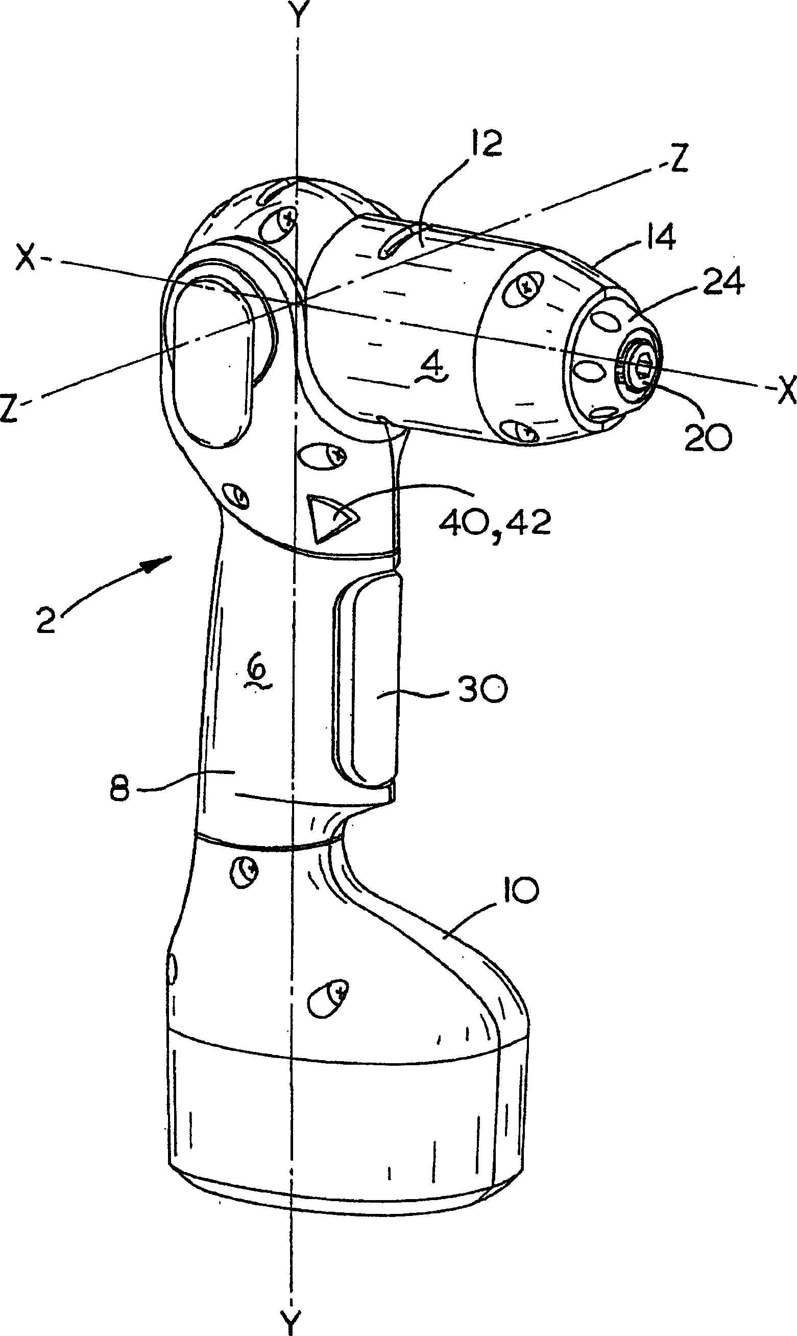
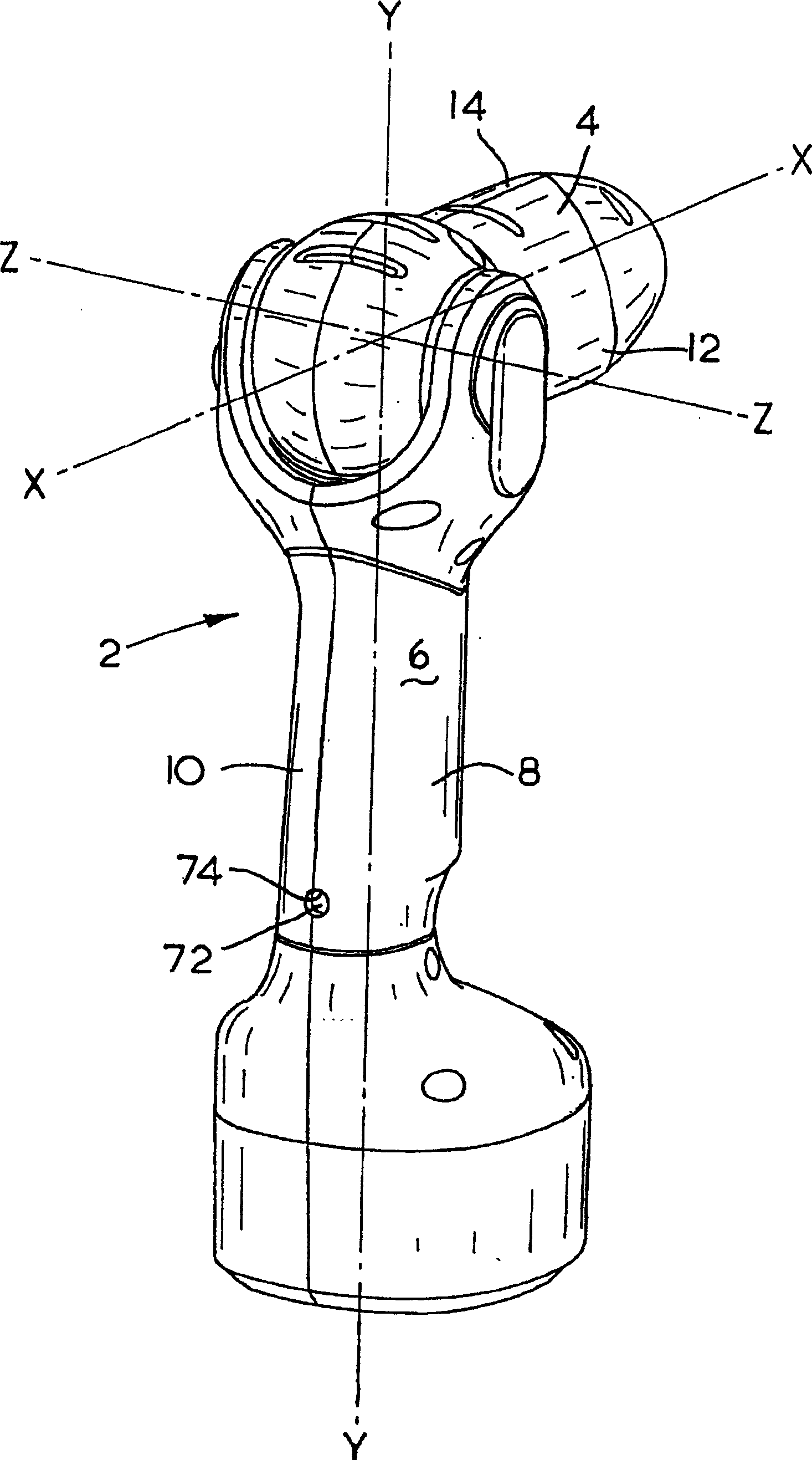
[0041] see figure 2 and 3 , an electric tool, generally indicated by reference numeral 2, which is an electric drill consisting of a cylindrical drill bit 4 and an elongated handle 6, said drill bit having a longitudinal axis X, said handle disposed about a longitudinal axis Y . The drill bit 4 is pivotally mounted on the handle 6 and pivots around an axis Z relative to the handle 6 . The handle 6 is formed by a first housing 8 and a second housing 10, which are connected by a number of screws (not shown). The drill bit 4 is formed by a third housing 12 and a fourth housing 14, which are connected by a plurality of screws (not shown).

[0042] Referring to FIGS. 4 and 5 , the drill bit 4 is composed of a motor 16 and a transmission gearbox (not shown) with an output shaft 20 . The motor 16 and gearbox are housed in the drill head 4 . The front end of the drill bit 4 is provided with a cylindrical gearbox housing 22, which surrounds the gearbox and the output shaft 20. T...


PUM


Abstract

A power tool ( 2 ) comprising a handle ( 6 ), a tool body ( 4 ) pivotably coupled to the handle ( 6 ) by a pivot ( 76, 78, 102, 104 ), a motor ( 16 ) mechanically coupled to a rotary output ( 20 ) housed in the tool body ( 4 ), a trigger switch ( 32 ) housed in the handle ( 6 ) and a locking mechanism for permitting or preventing pivotal movement of the tool body ( 4 ) relative to the handle ( 6 ), wherein an electrical connection ( 36,38 ) between the handle ( 6 ) and the tool body ( 4 ) passes through the pivot ( 76,78,102,104 ).

Description

technical field [0001] The present invention relates to power tools, and more particularly to an electric drill comprising a handle and a pivotable bit with an electrical connection between the handle and the bit. Background technique [0002] In the prior art, electric drills and electric screwdrivers are well known. Attempts have been made to combine a power drill and a power screwdriver, resulting in a power tool similar to existing power drills, with additional features that slow down and control the screw drive. attached figure 1 One such power tool is shown, known as a drill-driver. The drill-driver includes a main body having a bit and a handle portion fitted to the bit at a generally perpendicular angle. The drill head encapsulates a motor and a gearbox, and the handle portion defines a conventional pistol handle that is held by a user. The handle section includes a variable speed trigger switch that outputs low speed rotary motion in screw driving mode and high ...

Claims


Application Information

Patent Timeline
IPC IPC(8): H01R35/02
CPCH01R35/02
Inventor G·博恩
Owner BLACK & DECKER INC
Why Eureka
Try Eureka