
Method and apparatus for reducing image noise

A noise and image technology, applied in the field of image noise reduction, can solve the problems of image details disappearing, noise increase, etc., to achieve the effect of reducing image noise

Inactive Publication Date: 2003-12-10
SONY CORP
View PDF0 Cites 1 Cited by
  • Summary
  • Abstract
  • Description
  • Claims
  • Application Information

AI Technical Summary

Problems solved by technology

That is, noise increases when operations are not performed, or image detail disappears when operations are performed depending on the content of the object

Method used


Image

  • Method and apparatus for reducing image noise
  • Method and apparatus for reducing image noise
  • Method and apparatus for reducing image noise

Examples


Embodiment Construction

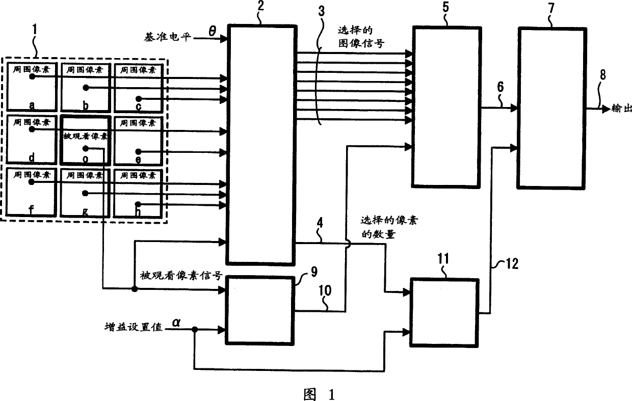
[0027] Hereinafter, the present invention will be described in detail with reference to the drawings. FIG. 1 is a block diagram of the configuration of one embodiment of a selection circuit for applying the image noise reduction method and apparatus of the present invention. In FIG. 1, parts corresponding to those in FIG. 5 have the same symbols.

[0028] In Figure 1, Mode 1 shows a specific point in the same image region as in Figure 5 that images the viewed pixel o and its surrounding pixels a, b, c, d, e, f, g, and state of h. Also, when the level values ​​of these pixels are replaced with the same symbols a to h and o, the level values ​​a to h of these surrounding pixels are supplied to the selection circuit 2 . And, the above-mentioned value of the reference level θ and the level value o of the pixel to be viewed are input to the selection circuit 2 .

[0029]In the selection circuit 2, the absolute value (|a-o|) of the difference between the level value a of the surr...


PUM


Abstract

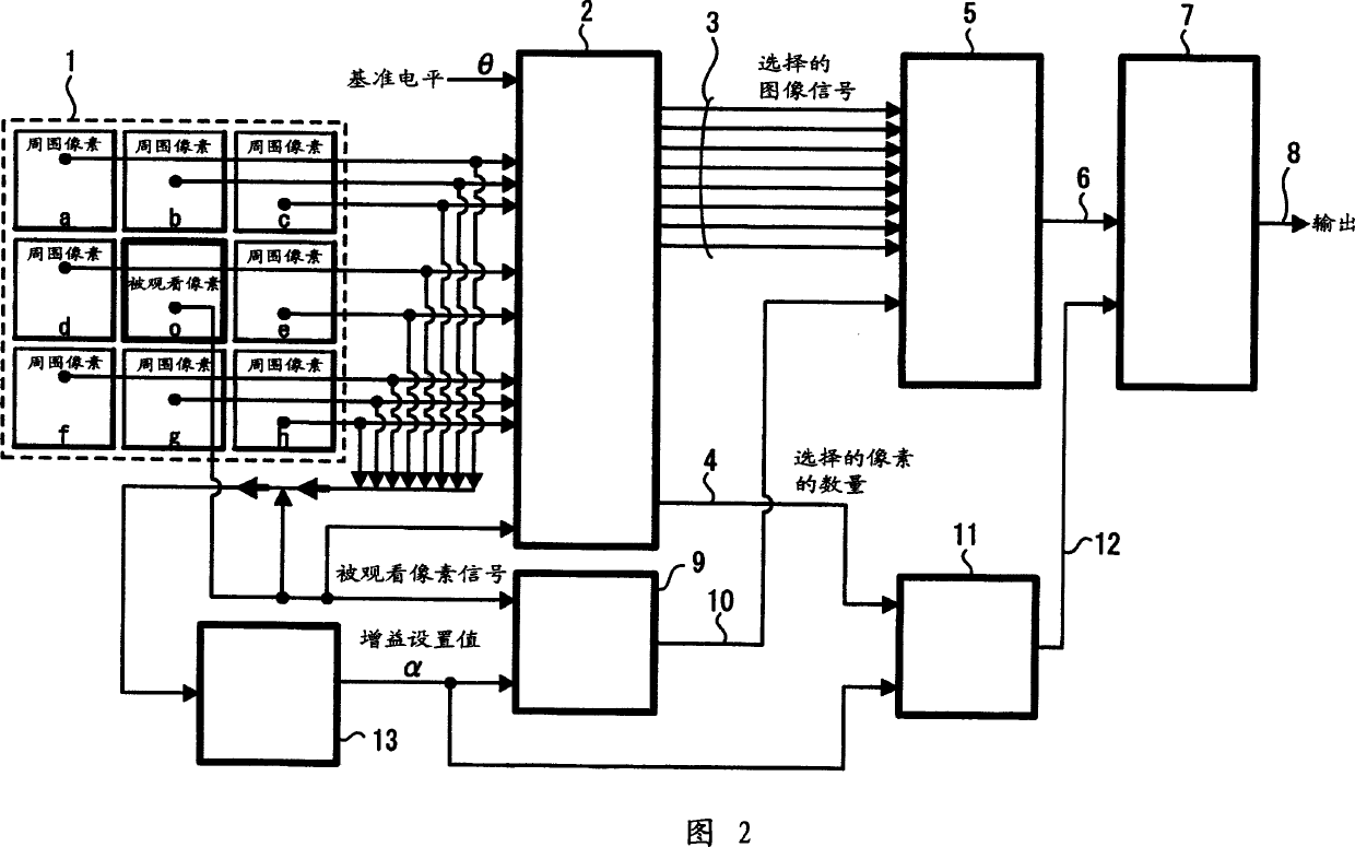
The present invention relates to an image reduction method and apparatus to be preferably used to digitize and process, for example, an image signal. Therefore, in the case of the present invention, level values a to h of peripheral pixels of a pattern 1, the level value o of a watched pixel, and the value of a reference level &thetas; are input and level values a to h in which absolute values for differences between level values of peripheral pixels and the watched pixel are smaller than the value of the reference level &thetas; are output to output ports 3. Moreover, the value of the number of output ports 3 to which level values a to h is output to an output port 4. Moreover, the level value o of the watched pixel is supplied to a multiplier 9 and multiplied by an optional gain set value alpha , and the multiplication value is supplied to an adder 5 and added with the level values a to h output from the output ports 3 of a selection circuit 2 and the addition value is supplied to a divider 7. Furthermore, the gain set value alpha is supplied to an adder 11 and added with a value output from the output port 4 of the selection circuit 2 and the addition value is supplied to the divider 7. Then, a value output from the adder 5 is divided by a value output from the adder 11 and the value of the operation result is derived from an output port 8. Thereby, the degree of signal processing is optionally set by the so-called epsilon -filter and the rate of watched pixels relating to the averaging operation is controlled and thereby, it is possible to optionally set the degree of signal processing and perform optimum image processing.

Description

technical field [0001] The invention relates to a method and a device for reducing image noise, preferably for processing eg image signals by digitization. In particular, the present invention relates to a method and apparatus for reducing image noise for solving problems encountered when reducing the noise component of an image signal using a so-called ε filter. Background technique [0002] For example, in order to reduce noise components included in image signals, various methods have been proposed so far. Specifically, one of the simplest methods with a large noise reduction effect is a method using a low-pass filter (hereinafter referred to as LPF). The LPF is a device for transmitting a signal having only components lower than a reference frequency. That is, by inputting a signal whose frequency is changed to the LPF and observing the amplitude of the output signal, the characteristic that the level of the high-frequency component is reduced can be obtained. [0003...

Claims


Application Information

Patent Timeline
Patent Type & Authority Applications(China)
IPC IPC(8): G06T5/00G06T5/20H04N1/409H04N5/21
CPCG06T5/20G06T5/002G06T2207/20192H04N1/409
Inventor 中岛健三井敏
Owner SONY CORP
Learn More