Disk supporter, disk holder and disk device
一种支承装置、保持装置的技术,应用在的盘装置,盘装置领域,能够解决脱出等问题,达到缩小空间、消除夹持错误、缩小面积的效果
- Summary
- Abstract
- Description
- Claims
- Application Information
AI Technical Summary
Problems solved by technology
Method used
Image

Examples
no. 1 example
[0168] Hereinafter, a disk supporting device, a disk holding device, and a disk device according to a first embodiment of the present invention will be described with reference to FIGS. 1 to 6 . The disk device of this embodiment is an example of a disk changer incorporated in a component stereo.
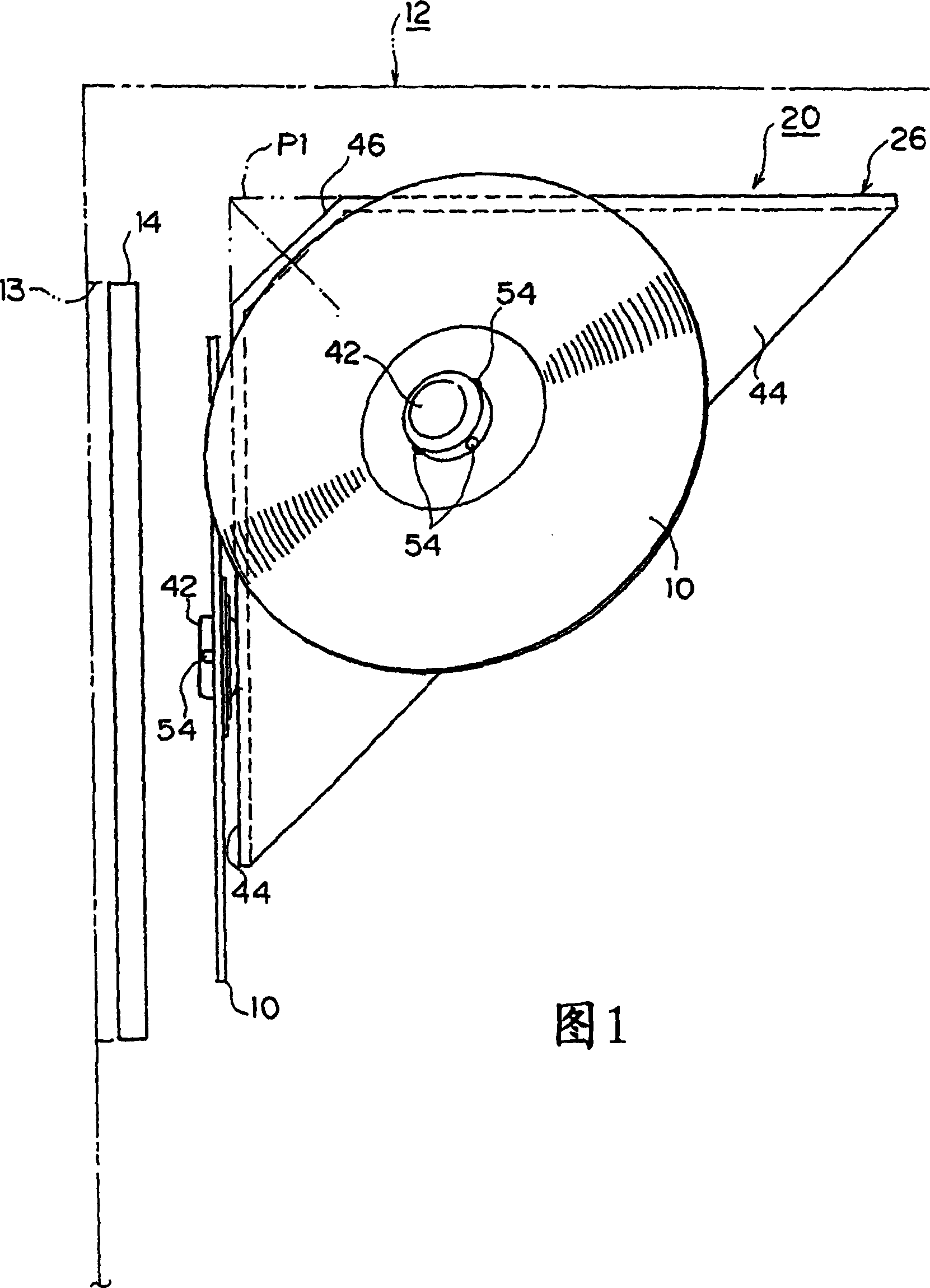
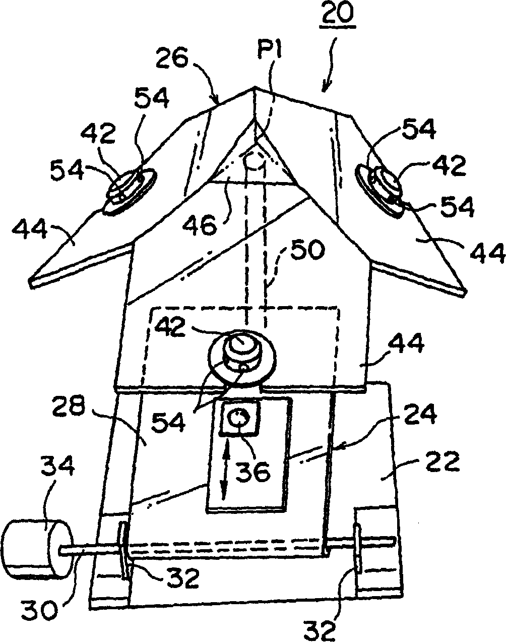
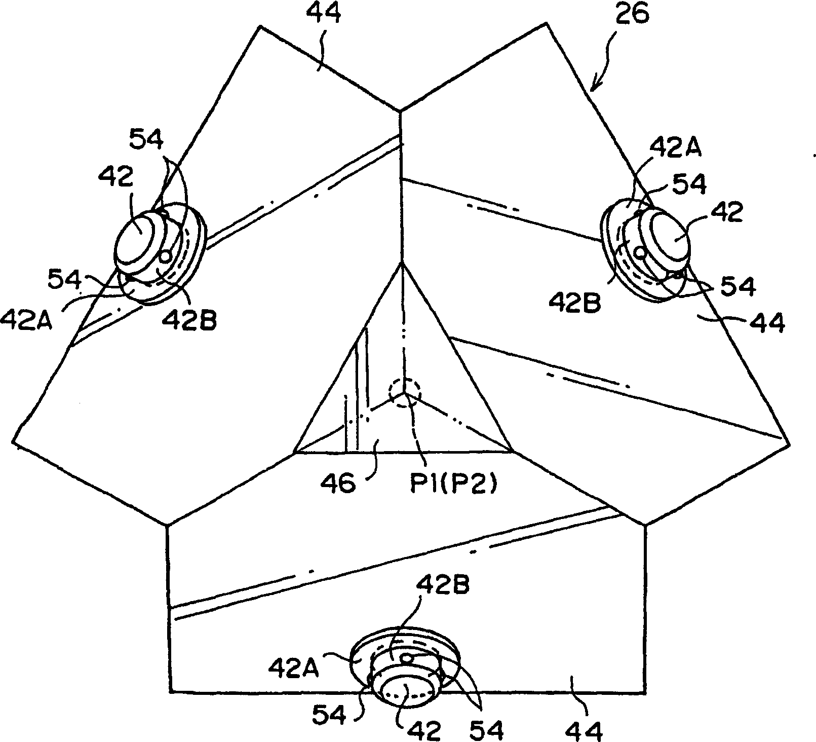
[0169] Fig. 1 shows a schematic diagram of the positional relationship between the disc changer and the door arranged in the combined stereo system, figure 2 It is an overall perspective view of the main part of the disc changer shown in FIG. 1, image 3 yes figure 2 The top view of the turntable shown in Figure 4 is image 3 A cross-sectional view of the turntable shown, Figure 5 yes image 3 Front view of the support portion of the turntable shown.
[0170] (Overall composition of combined stereo system)
[0171] As shown in FIG. 1, a disc changer 20 is housed in a housing 12 of a combined stereo system (hereinafter simply referred to as "stereo system"). Further, a substa...
no. 2 example
[0254] Below, according to Figure 19 ˜ FIG. 49 describe the second embodiment of the present invention, that is, the disk device. The disc device of this embodiment is an example of a disc changer incorporated into a component stereo system.
[0255] Figure 19 It is a top view of the disk changer configured in the combined stereo system, and Fig. 20 is a cut-off Figure 19 Fig. 21 is an explanatory diagram illustrating the drive path of the tray shown in Fig. 20, Figure 22 is a top view of the drive path shown in Figure 21, Figure 23 It is a bottom view of the tray shown in FIG. 21 .
[0256] (Overall composition of combined stereo system)
[0257] In the casing 112 (refer to the two-dot dash line in Fig. 20 ) of the combined stereo system (hereinafter simply referred to as "stereo system") Figure 19 In the disc changer 120 as shown, and as shown in FIG. In addition, a door 114 is slidably arranged corresponding to the opening 13 on the stereo.
[0258] In additio...
no. 3 example
[0393] according to Figure 50 ~ Figure 52 The configuration of the third embodiment will be described. This embodiment is to make Figure 19 And the example in which the disk changer 120 as a whole shown in FIG. 20 is tilted relative to the casing 112 . In this embodiment, the same reference numerals are assigned to the same parts as those in the second embodiment. and, Figure 50 and Figure 51 The disc changer 120 shown represents only the main parts of the disc changer 120 of the third embodiment.
[0394] Such as Figure 50 and Figure 51 As shown, in this embodiment there is a rotatable support Figure 19 And the overall supporting device 210 of the disc changer 120 shown in FIG. 20 . On the front side of the support device 210, a pair of bearing portions 212 for pivotally supporting the spindle 130 of the disc changer 120 are formed at both left and right ends. Therefore, the front portion of the disc changer 120 rotates around the spindle 130 .
[0395] In ad...
PUM
 Abstract
Description
Claims
Application Information
 - R&D
- Intellectual Property
- Life Sciences
- Materials
- Tech Scout
- Unparalleled Data Quality
- Higher Quality Content
- 60% Fewer Hallucinations
Browse by: Latest US Patents, China's latest patents, Technical Efficacy Thesaurus, Application Domain, Technology Topic, Popular Technical Reports.
© 2025 PatSnap. All rights reserved.Legal|Privacy policy|Modern Slavery Act Transparency Statement|Sitemap|About US| Contact US: help@patsnap.com