Actuator arrangements

An actuator device and actuator technology are applied in transportation and packaging, hydraulic equipment for manipulating turnouts or line breakers, electrical equipment for manipulating turnouts or line breakers, etc., which can solve the problem of interrupting railway traffic , Dangerous signals and other issues

Inactive Publication Date: 2004-04-07
GENERAL SIGNAL UK
View PDF0 Cites 2 Cited by
  • Summary
  • Abstract
  • Description
  • Claims
  • Application Information

AI Technical Summary

Problems solved by technology

This can lead to red flags on track...

Method used


Image

  • Actuator arrangements
  • Actuator arrangements
  • Actuator arrangements

Examples


Embodiment Construction

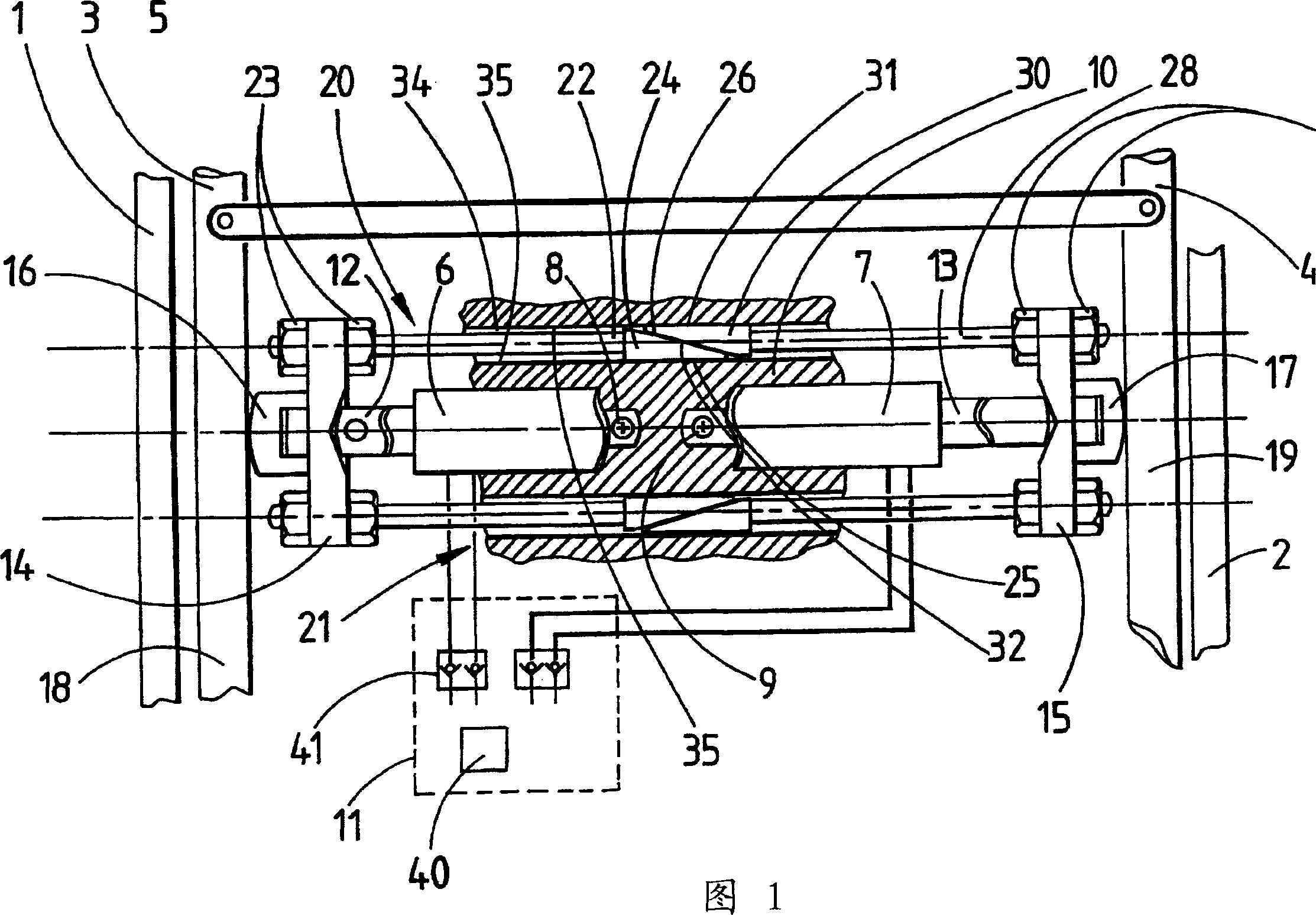
[0010] Referring to Figures 1 and 2, the actuator arrangement is located between a pair of fixed main rails 1 and 2 and a pair of movable members extending between said main rails in the form of a pair of Switch rails 3 and 4. A connecting bar or gauge bar 5 extending transversely between the two switch rails connects the two switch rails together.

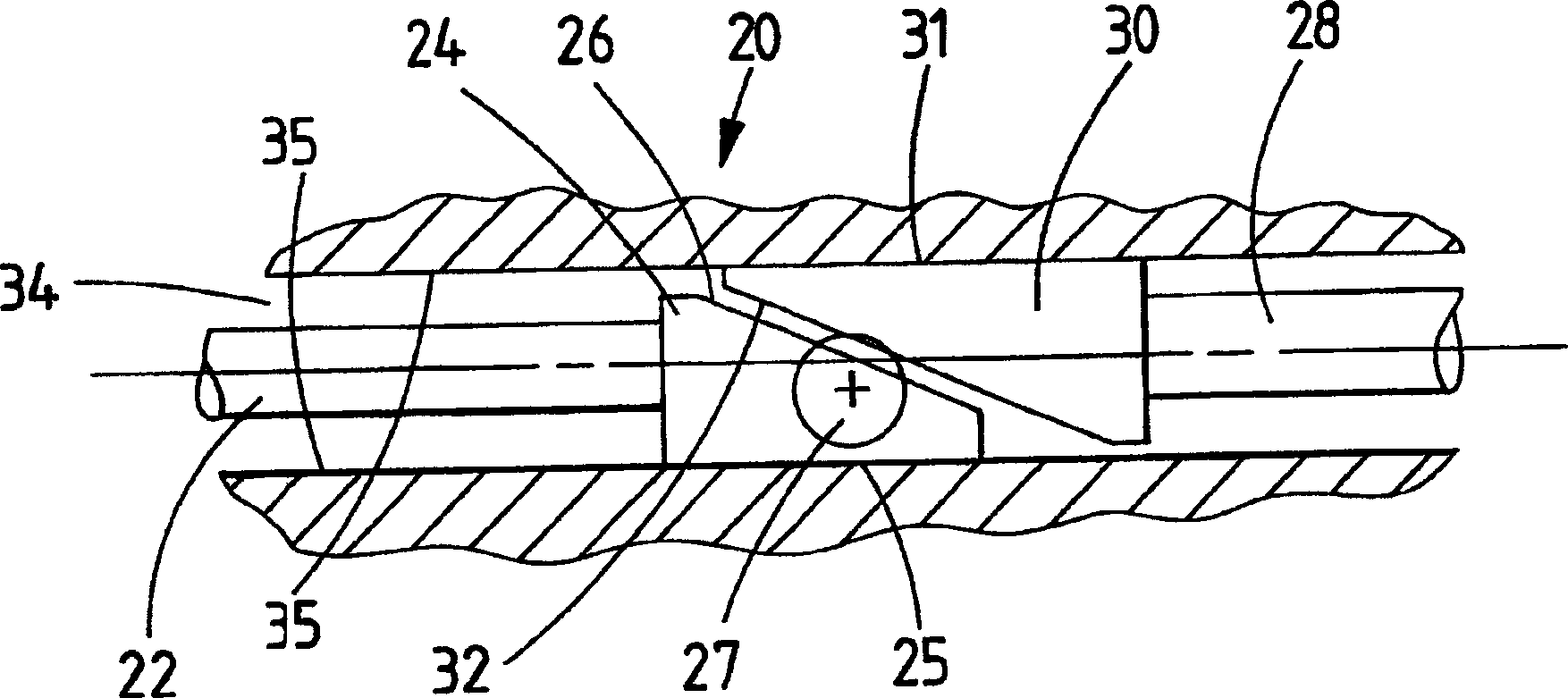
[0011] This actuator arrangement consists of two conventional hydraulic actuating cylinders 6 and 7 fixed at their bases 8 and 9 to a sleeper 10 or other fixed structure, the two hydraulic actuating cylinders 6 and 7 being aligned with each other , extending laterally outward. Cylinders 6 and 7 are driven by fluid from a conventional hydraulic source, indicated generally at 11 . Pistons 12 and 13 of cylinders 6 and 7 support brackets 14 and 15 respectively, and insulating nylon brushes 16 and 17 are respectively provided on the outside of the brackets. The brushes 16 and 17 bear against the inner surfaces 18 and 19 of the switc...


PUM


Abstract

An actuator arrangement for moving first and second members (3, 4), the two members (3, 4) being interconnected with one another by a linkage (5) extending between them. The arrangement comprises first and second actuator means (6, 7) arranged to bear against respective movable members (3, 4) such that actuation of the first actuator (6) causes both movable members (3, 4) to move in one direction and actuation of the other actuator (7) causes both movable members (3, 4) to move in the opposite direction. A locking mechanism (20, 21) is coupled with the first and second actuators (6, 7) and is so arranged as to allow free movement in opposite directions caused by actuation of the first and second actuator means respectively but to prevent movement in either direction when not caused by actuation of the respective actuator means.

Description

technical field [0001] The invention relates to an actuator device. Background technique [0002] Various actuator arrangements are employed on railway switches or switch linkages. A main drive actuator abuts against the switch track near the free end or tip of the switch track, the function of which is to push the track to the side of the home rail. In the case of a switch rail with a long curved section, there must be one, two, or even up to three additional actuators, or counter-drive actuators, which are spaced apart from each other along the switch rail , in order to push the switch rail, or keep it in the correct position relative to the rail. The main drive actuator typically includes some form of catch or lock that securely locks the switch rail relative to the home rail. This ensures that the switch rail remains in the correct position even when the force exerted by the actuator itself should lower it. Since the switch may remain in the switched position for a l...

Claims


Application Information

Patent Timeline
IPC IPC(8): B61L5/04B61L5/06B61L5/10
CPCB61L5/10B61L5/06B61L5/04
Inventor 安东尼·R·戴维斯
Owner GENERAL SIGNAL UK
Why Eureka
Try Eureka