

Photoelectric input pen
An input pen and photoelectric technology, which is applied in the input/output process of data processing, electrical digital data processing, instruments, etc., can solve the problems of inconvenient use of the handwriting board and the function limitation of the mouse, and achieve the effect of reasonable structure and convenient use.
- Summary
- Abstract
- Description
- Claims
- Application Information
AI Technical Summary
Problems solved by technology
Method used
Image

Examples
Embodiment 1
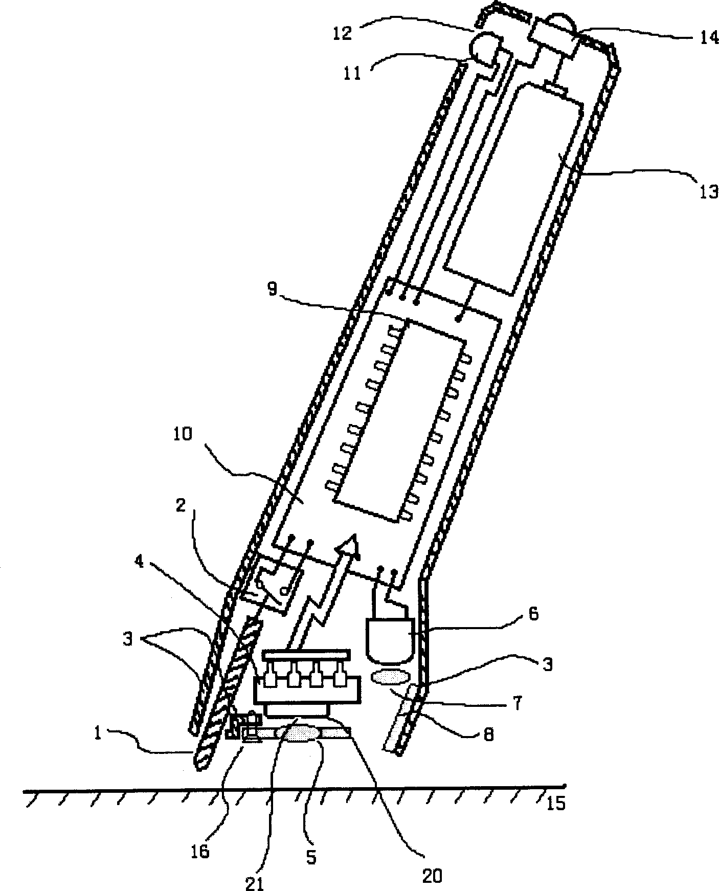
[0021] Embodiment 1: The structure of the wireless input pen is as attached figure 1 As shown, it shows the main installation and connection relationship of each component. Among them: 1-pen tip; 2-pressure sensor can use a reed contact micro switch, the pen tip can move appropriately in the axial direction, and stand on the end of the movable contact of the micro switch, and the micro switch is usually under the action of the spring force of the reed In the disconnected state, the action stroke and elastic force of the switch should be as small as possible, so as to adapt to the feeling habit of writing when writing by hand. In this embodiment, the nib pressure sensor is simply composed of the above two parts; 3-wireless input pen shell; 4- Schematic diagram of the optical motion sensor. The ready-made product can be the ADNS-2620 optical mouse sensor from Aglent Technologies in the United States, which includes an image acquisition system (IAS), a digital signal processor (D...
Embodiment 2
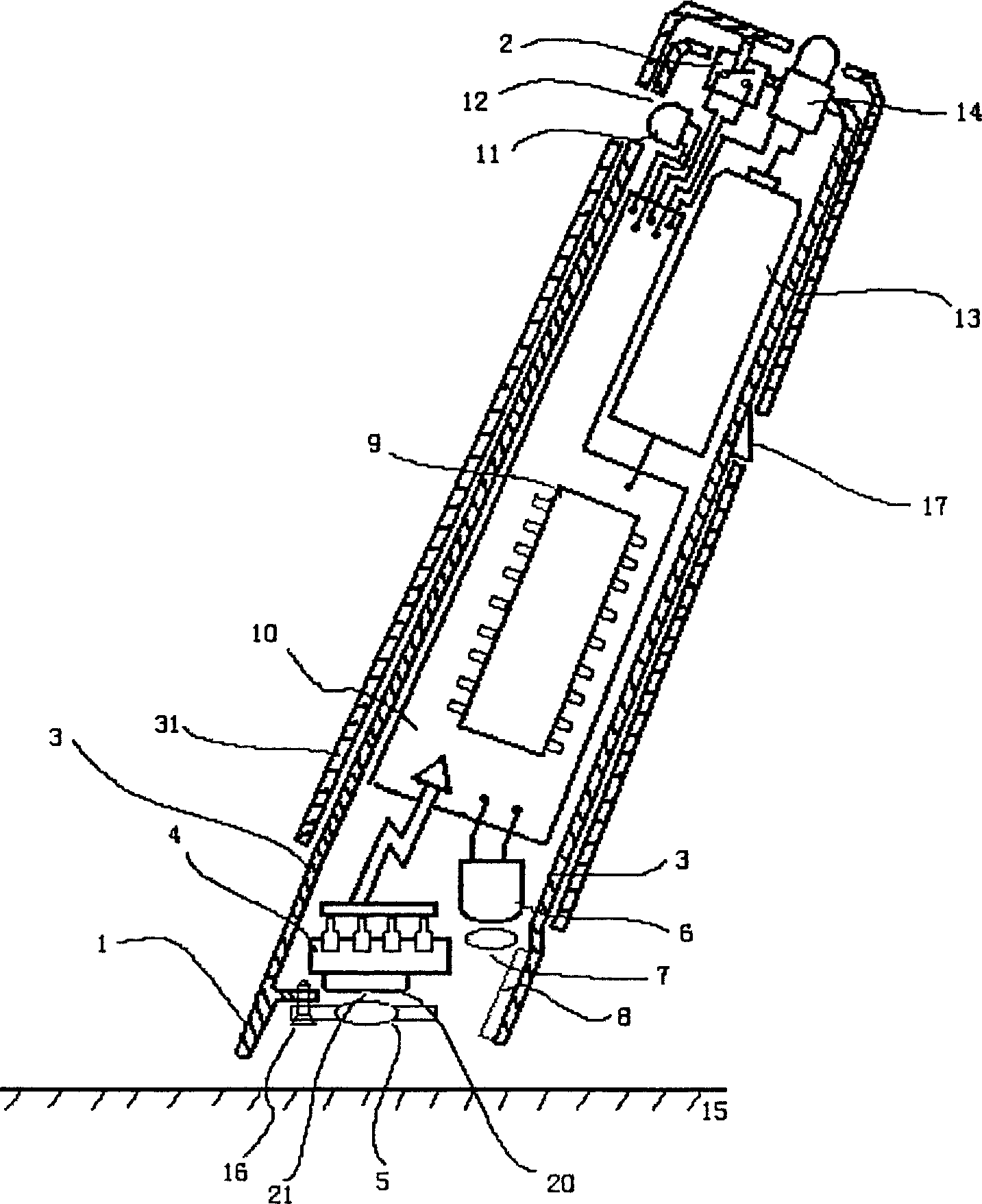
[0022] Embodiment 2: Since the movable nib 1 has a moving stroke when it acts on the nib pressure sensor, it may have an adverse effect on the effective induction of the mobile sensor with a small depth of field. The present invention can also adopt a sleeve structure in which the nib is fixed relative to the sensor : The nib 1 is only a protruding part of the front end of the pen shell 3, the front end of the shell with a fixed nib is equipped with an optical movement sensor 4, the inside of which is provided with a peripheral controller 9 and a circuit board 10, and 31 sets of pen bodies held by hand In the shell 3, the two can slide relative to each other in the axial direction, and the sliding range is limited by the bayonet pin 17 with a reed. The nib pressure sensor 2 is placed at the tail end of the shell 3, and a push-button power switch 14 ( See attached figure 2 ).
Embodiment 3
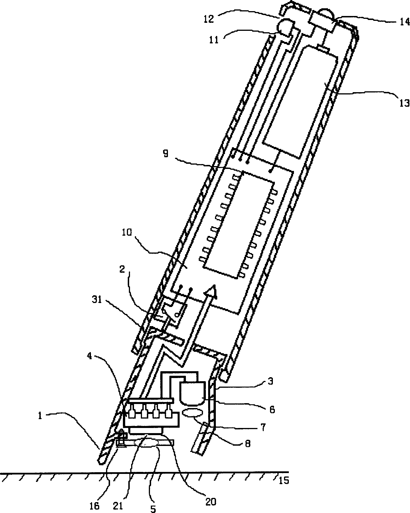
[0023] Embodiment 3: the shell 3 can also be used as attached image 3The shown shorter structure only houses the optical movement sensor 4 and its combination, the circuit board 10 and other devices are in the pen body 31 for holding, and the optical movement sensor chip pins are passed through flexible cables or brushes. connected to? On the circuit board 10 in the pen body 31 , the pen tip 1 is integrated with the shell 3 , and the pressure sensor 2 is fixed in the pen body 31 and mechanically connected with the tail end of the shell 3 . attached figure 2 And attached image 3 The rest of the number descriptions and appended figure 1 Similarly, after the tip of the pen touches the surface 15 of the object, the casing 3 is shrunk toward the inside of the pen body, causing the pressure sensor 2 to output a signal under pressure. Within the most effective depth of field range, it can also be adjusted at the edge of the effective depth of field range to maximize the effect...
PUM
 Abstract
Description
Claims
Application Information