Check patentability & draft patents in minutes with Patsnap Eureka AI!

Coding method and device

A technique of sums, codewords, applied in the field of coding and devices

Inactive Publication Date: 2004-12-08
KODA INVESTMENTS
View PDF3 Cites 0 Cited by
  • Summary
  • Abstract
  • Description
  • Claims
  • Application Information

AI Technical Summary

Problems solved by technology

[0024] Although the EFMPlus described in US-A-5,917,857 and the encoding method described in US-A-5,790,056 both provide 17 / 16 improvements, but they require excess storage capacity for primary and alternate conversion tables

Method used


Image

  • Coding method and device
  • Coding method and device
  • Coding method and device

Examples


Embodiment Construction

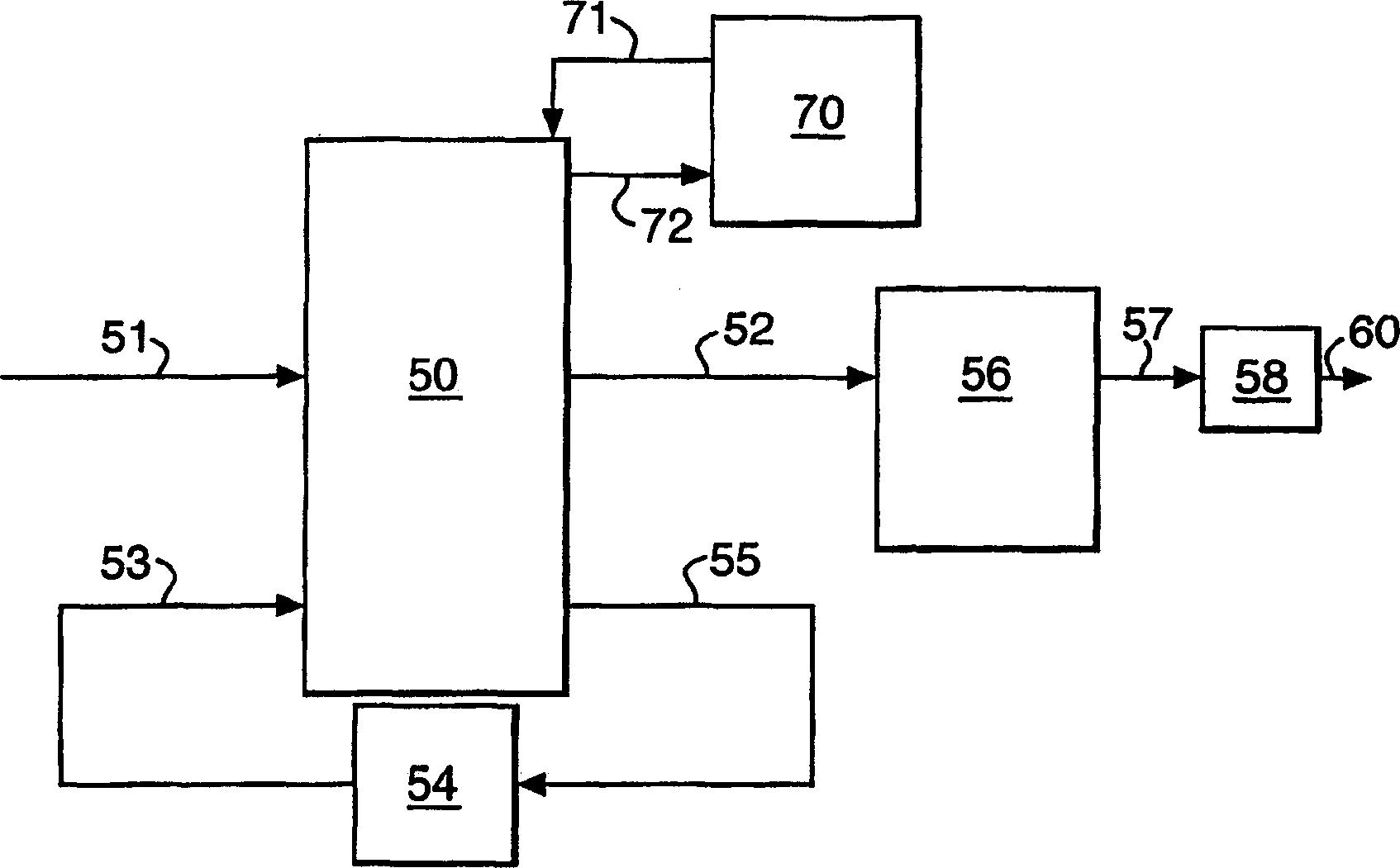
[0053] figure 1 An encoder for converting m-bit information words into n-bit codewords is shown, comprising a converter 50 connected to a bus 51 of m-bit width for receiving m-bit information words and connected to n A bit-wide bus 52 is used to transfer the converted n-bit codeword. In this example, m is 8 and n is 16.

[0054] In addition, the converter 50 is connected to a bus 53 with a width of s bits for receiving an encoder current state value representing the instantaneous encoding state, and to a bus 55 with a width of s bits for transmitting the next state of the encoder value. In this example, the number of possible encoder states is 4, and s is 2.

[0055] The s-bit current state value is stored by the buffer memory 54, for example comprising s flip-flops. The buffer memory 54 is connected to a bus 55 for receiving the next state value from the converter 50 and to a bus 53 for transmitting the current state value currently stored in the buffer memory 54 .

[00...


PUM


Abstract

method for converting a succession of data words into an output bit stream comprising a succession of code words uses a table of code words and associated next state values. For each data word the table provides a code word and associated next state value for each of a plurality of present stat e values. The code words are either of a first type that correspond to only on e data word or of a second type that correspond to more than one data word. Th e next state value associated with each code word of the second type belongs t o one of a first group of states. The next state values ensure that adjacent code words chosen in accordance with the next state values satisfy a run length constraint. Code words belonging to the first group of states can be identified by a unique bit structure.

Description

technical field [0001] The present invention relates to a method and apparatus for encoding a series of m-bit information words into a series of n-bit code words for subsequent modulation, where m is an integer and n is an integer greater than m. Background technique [0002] Run-length constraint codes, often designated as (d,k) codes, have been widely and successfully applied in modern magnetic and optical recording systems. Such codes and means for implementing said codes are described in detail by K.A. Schouhamer Immink in the book entitled "Code for Mass Data Storage Systems" (ISBN 90-74249-23-X, 1999). [0003] Run-length constraint codes are an extension of earlier non-return-to-zero recording codes in which a recorded binary 0 is represented by no change in the magnetic flux of the recording medium and a recorded binary 1 is represented by a change from one direction of the magnetic flux to the opposite direction. expressed by transformation. [0004] In a (d, k) c...

Claims


Application Information

Patent Timeline
IPC IPC(8): G11B20/14H03M5/14H03M7/14H03M7/46
CPCH03M7/46G11B20/1426H03M5/145
Inventor 海斯·J·范登恩丁
Owner KODA INVESTMENTS
Features
  • R&D
  • Intellectual Property
  • Life Sciences
  • Materials
  • Tech Scout
  • Unparalleled Data Quality
  • Higher Quality Content
  • 60% Fewer Hallucinations
Learn More