Optical head apparatus and optical disk apparatus using this optical head apparatus

A technology of optical head and equipment, which is applied in the direction of optical recording head, head configuration/installation, optical recording/reproduction, etc. It can solve the problems of enlarging the shape of the coil, reducing the sensitivity due to the total weight, and increasing the size of the movable part.

Inactive Publication Date: 2004-12-29
KK TOSHIBA
View PDF1 Cites 0 Cited by
  • Summary
  • Abstract
  • Description
  • Claims
  • Application Information

AI Technical Summary

Problems solved by technology

It should be noted that insulating cladding is required, and obviously this is a bulk factor
[0009] In addition, arranging one of the coils (magnetic circuit) as a heavy load at a position away from the center of gravity causes a problem that the sensitivity decreases due to an increase in the total weight
[0010] On the other hand, when a plurality of yokes are also arranged inside the coil according to the current direction in order to improve the efficiency of using the current flowing through the coil as a drive force, not only the coil shape is enlarged, but also the usability is unfavorably increased. The size of the moving part

Method used


Image

  • Optical head apparatus and optical disk apparatus using this optical head apparatus
  • Optical head apparatus and optical disk apparatus using this optical head apparatus
  • Optical head apparatus and optical disk apparatus using this optical head apparatus

Examples


Embodiment Construction

[0038] Embodiments of the present invention will now be described in detail with reference to the accompanying drawings.

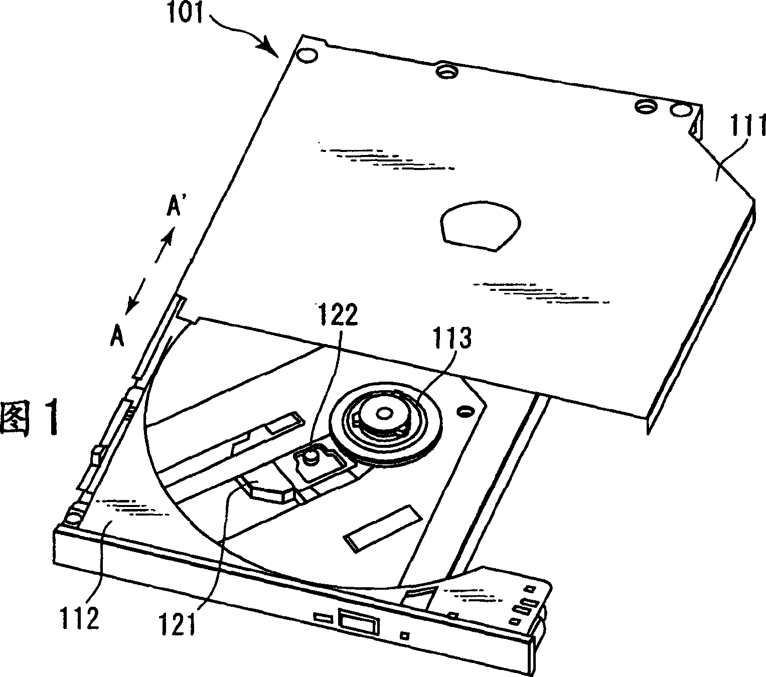
[0039] FIG. 1 shows an example of an optical disc device including an optical head device according to the present invention.

[0040] As shown in FIG. 1 , an optical disk device 101 has a casing 111 and a tray unit 112 formed to be capable of performing an ejection operation (movement in a direction shown by an arrow A) or a loading operation (movement in a direction shown by an arrow A') with respect to the casing 111. direction shown).

[0041] At a substantially central portion of the tray unit 112 is provided a turntable 113 that rotates the optical disc D at a predetermined number of revolutions. It should be noted that when the optical disc is not loaded in the state where the tray unit 112 is ejected, the optical head device 121 and the objective lens 122 introduced into the optical head device 121 can be seen without covering.
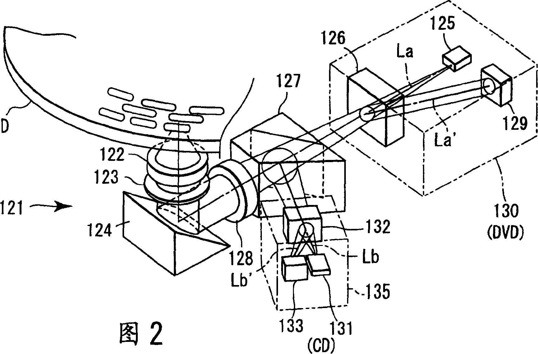
[0042] 2 is a sc...


PUM


Abstract

A magnetic body 311 positioned almost in the gravity center of an actuator is sandwiched between two magnets 321, 322 to secure two magnetic circuits, and a focusing coil 312 and a tracking coil 313 are arranged between the magnetic body and both magnets. Thus, a driving force symmetrical with the magnetic body as a center are obtained.

Description

technical field [0001] The present invention relates to an optical head and an optical disc device, which are used for recording or reproducing information in an optical disc as an information recording medium. Background technique [0002] In recent years, in information recording / reproducing apparatuses (optical disc apparatuses), there have been increasing demands for an increase in double speed so as to be able to record information at a high double speed such as 8 to 48 times, downsizing, and the like. Therefore, strict design conditions are applied to an optical disc device that records information in an optical disc or restores information from the optical disc. [0003] In particular, the actuator is required to be capable of high-speed access, that is, to have high sensitivity. The sensitivity (AC sensitivity) of the actuator is obtained as follows. [0004] AC Sensitivity=F / m, F=Biln [0005] F is the kinetic energy and m is the mass of the movable part of the a...

Claims


Application Information

Patent Timeline
Patent Type & Authority Applications(China)
IPC IPC(8): G11B7/09G11B7/085
CPCG11B7/0935G11B7/08582
Inventor 篠塚启司
Owner KK TOSHIBA
Why Eureka
Try Eureka