Method and device for producing laminate

A manufacturing method and lamination device technology, which can be applied to lamination devices, manufacturing tools, additive manufacturing, etc., and can solve problems such as component parts falling off

Inactive Publication Date: 2005-01-05
INST OF TECH PRECISION ELECTRICAL DISCHARGE WORKS
View PDF1 Cites 15 Cited by
  • Summary
  • Abstract
  • Description
  • Claims
  • Application Information

AI Technical Summary

Problems solved by technology

That is, the components after punching are fixed relative to the punching hole only by the frictional force against the punching hole. Therefore, due to vibration and other reasons during the sequential transfer of the processed material, the component parts fall off from the punching hole and have to be fixed. Interrupt sequential transfer processing
[0009] In addition, once the component is pushed back in order to return the component to the punched hole, some deformation or dimensional change will occur

Method used


Image

  • Method and device for producing laminate
  • Method and device for producing laminate
  • Method and device for producing laminate

Examples


Embodiment Construction

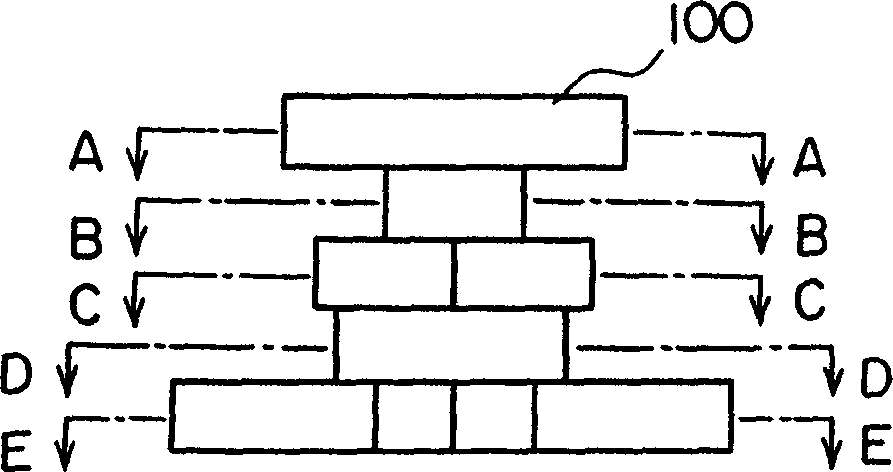
[0050] Fig. 3 is an explanatory diagram showing a laminated body and constituent members in an embodiment of the present invention, (a) and (b) are the front and plane faces of each laminated body, and (c) to (g) are diagrams of constituent members constituting each laminated body top view.

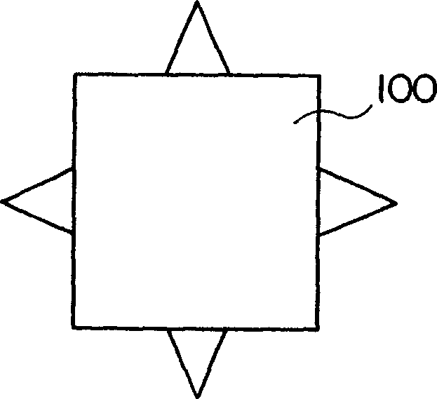
[0051] In FIG. 3, the laminated body 100 is, for example, an object having substantially the same shape as that shown in FIG. ), the component has an outline corresponding to the cross-sectional shape at each height position.

[0052] 106 is a pin hole (also called a half-piercing hole), which is formed in the same relative position and with the same shape and size in the middle part of the plane of each component 101-105 by the following method. In addition, whether each constituent member 101-105 is one or a plurality of three or more, it can be appropriately selected according to the shape and dimension of the laminated body 100 .

[0053] Figure 4 It is an enlarged longitudinal sec...


PUM


Abstract

A method for producing a laminate where a plurality of compositional members having different cross-sectional shapes are formed continuously. A long material to be processed is fed forward in the longitudinal direction and a plurality of kinds of compositional members each having a contour corresponding to each cross-sectional shape of the laminate are molded by non-separable indenting such that at least a parts of their contour is stopped at the material to be worked. At the final stage of feeding forward the material to be worked; the compositional members are pushed out sequentially and laminated integrally.

Description

technical field [0001] The present invention relates to a manufacturing method and a manufacturing apparatus for continuously forming a laminated body of a plurality of constituent members having different cross-sectional shapes. Background technique [0002] FIG. 1 is an explanatory diagram showing a laminated body which is the object of the present invention. What (a) represents is a front view, what (b) represents is a top view, and Fig. 2 is a cross-sectional view at each position of Fig. 1 (a), and Fig. 2 (a) to Fig. 2 (e) represent Fig. 1 ( The A-A line section, B-B line section, C-C line section, D-D line section and E-E line section in a). [0003] Taking the laminated body 100 as shown in Figure 1 as an example, when made of iron and steel materials, the circular cross-section parts shown in (b) and (d) of Figure 2 can be processed by turning, as shown in Figure 2 (a ), (c), and (e) shown in the square, regular hexagon and similar cross-section parts not only requ...

Claims


Application Information

Patent Timeline
Patent Type & Authority Applications(China)
IPC IPC(8): B21D35/00B21D39/03B23D31/00B26F3/00B29C41/38B29C67/00
CPCB23D31/002B21D35/00B29C41/383B29C67/0074B21D39/03B26F3/002B29C64/141B29C64/147Y10T156/1056Y10T156/1062Y10T156/12Y10T156/1304B32B37/00B32B39/00
Inventor 二村昭二村田力
Owner INST OF TECH PRECISION ELECTRICAL DISCHARGE WORKS
Why Eureka
Try Eureka