

Apparatus for regulating gap between vehicle and platform
A gap adjustment device, technology for vehicles, applied in the direction of stations, passenger warning devices, transportation and packaging
- Summary
- Abstract
- Description
- Claims
- Application Information
AI Technical Summary
Problems solved by technology
Method used
Image

Examples
Embodiment approach 1
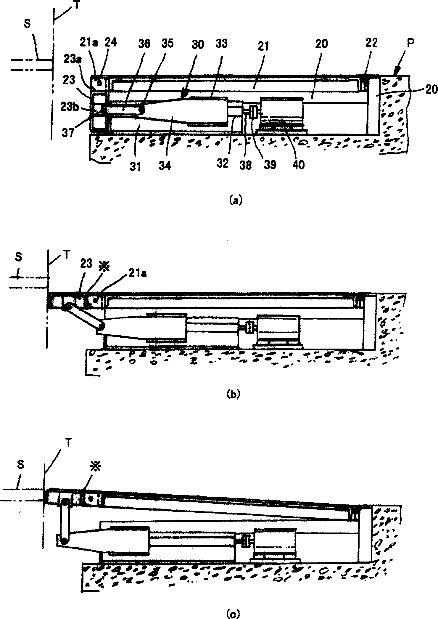
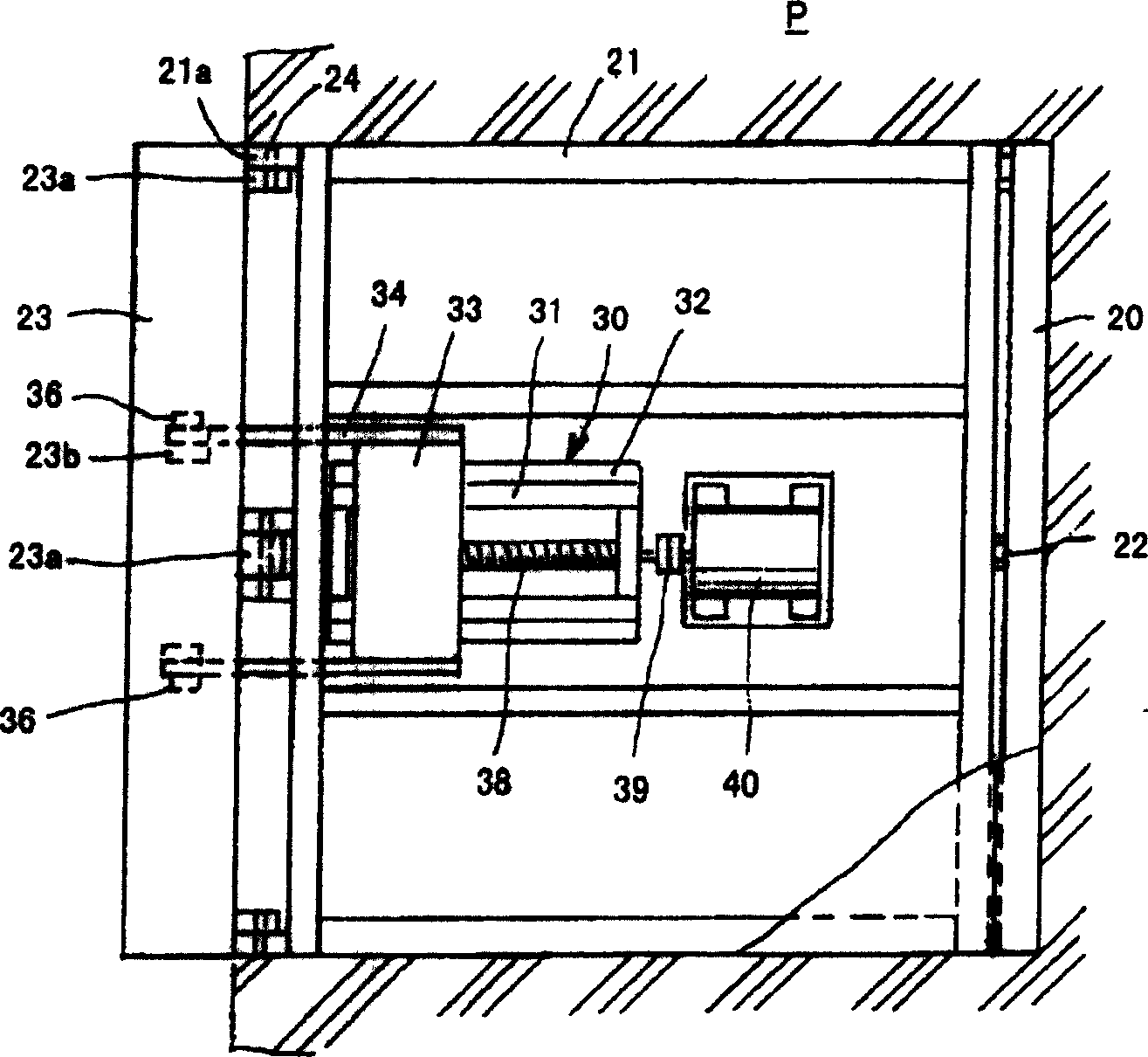
[0038] figure 1 and figure 2 Among them, a frame 20 is provided at the recess above the side of the platform P near the track. On the frame 20, a first pedal 21 is installed through a hinge 22 in a form that can swing up and down near the rail side. A bearing portion 21 a is provided at a front end portion of the first pedal 21 on the rail side, and the second pedal 23 is swingably attached via a bearing portion 23 a and a pin 24 .
[0039] A lift mechanism 30 is provided below the first step 21 . A mounting table 31 is fixed above the recess. A guide member 32 such as a linear guide rail is provided on the mounting table 31, and a slider 33 is slidably mounted thereon. One end of a support arm 34 is fixed to the side of the slider 33 . One end of a link 36 is rotatably attached to the other end of the support arm 34 by a pin 35 . The other end of the link 36 is rotatably attached to the bearing portion 23 b of the second pedal 23 with a pin 37 .
[0040] A screw shaf...
Embodiment approach 2
[0044] In the structure of the second embodiment of the present invention, compared with the first embodiment of the present invention, the structure of the first pedal is completely the same, and only the structure of the second pedal is different. Therefore, only the second pedal is shown and described.
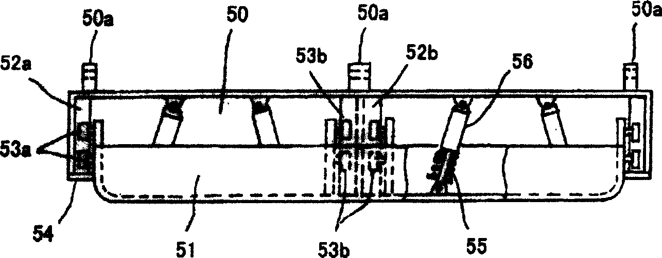
[0045] exist Figure 3 ~ Figure 5 Among them, the second pedal 50 is formed into a box shape with an open track side, and the third pedal 51 is slidably accommodated therein. On the second pedal is set for and figure 1 and figure 2 The bearing portion 50a to which the first pedal 21 is pinned is used for and figure 1 and figure 2 The above-mentioned bearing portion 50b to which the connecting rod 36 is pin-connected is the same as that of Embodiment 1 of the present invention.
[0046] A guide plate 52a is fixed to the side surface of the second step, and a guide plate 52b is fixed to the center. In addition, a guide wheel 53a is provided on the side surface of th...
Embodiment approach 3
[0055] Embodiment 3 of the present invention is compared with Embodiment 2 of the present invention in that the structure of the second pedal is the same, and only the structure of the third pedal and the pressurizing mechanism are different. Therefore, only the third pedal is shown and described.
[0056] exist Figure 6 and Figure 7 In the same way as in the second embodiment of the present invention, the third step 60 is slidably housed in the second step 50 . The second pedal 50 and the third pedal 60 are connected by an air cylinder 61 . Air is supplied to the air cylinder 61 from an air source not shown through the pipe 62, and the third pedal 60 is protruded toward the rail side or pulled back.
[0057] A roller 64 is rotatably supported by a shaft 63 at a corner of the third pedal 60 . The outer peripheral surface of the roller 64 protrudes slightly outward from the outer peripheral surface of the third pedal 60 .
[0058] After the second pedal 50 is tilted, the...
PUM
 Abstract
Description
Claims
Application Information