Engine

A technology for engines and diesel engines, which is applied to engine components, machines/engines, liquid fuel engines, etc. It can solve problems such as increased plunger stuck, carbon deposits in fuel injectors, and temperature differences, achieving simplified assembly and low cost , the effect of cheap manufacturing

Active Publication Date: 2005-02-09
MAN ENERGY SOLUTIONS SA
View PDF0 Cites 3 Cited by
  • Summary
  • Abstract
  • Description
  • Claims
  • Application Information

AI Technical Summary

Problems solved by technology

Here, therefore, a short-circuit flow can be produced between these two closely adjacent connecting channels, as a result, no strong flushing of the annulus by fresh fuel takes place, with the consequence that the fuel in the annulus becomes too hot, which can cause Injector carbon deposits
[0003] A further concern here is the unfavorable temperature distribution on the pump cylinder and the pump plunger's peripheral surface, which increases the risk of the plunger jamming so that the plunger cannot rotate any more during a load change.
Another disadvantage is that a temperature difference can also arise between the fuel injection pump which receives fuel first and the fuel injection pump which receives fuel last, which can lead to different combustion conditions and is thus also undesirable

Method used


Image

  • Engine
  • Engine
  • Engine

Examples


Embodiment Construction

[0015] The main field of application of the invention is large engines with fuel injection pumps, such as large diesel engines, which are used, for example, in ship drives or power plant drives or the like. The basic construction and operating principle of such devices are known per se.

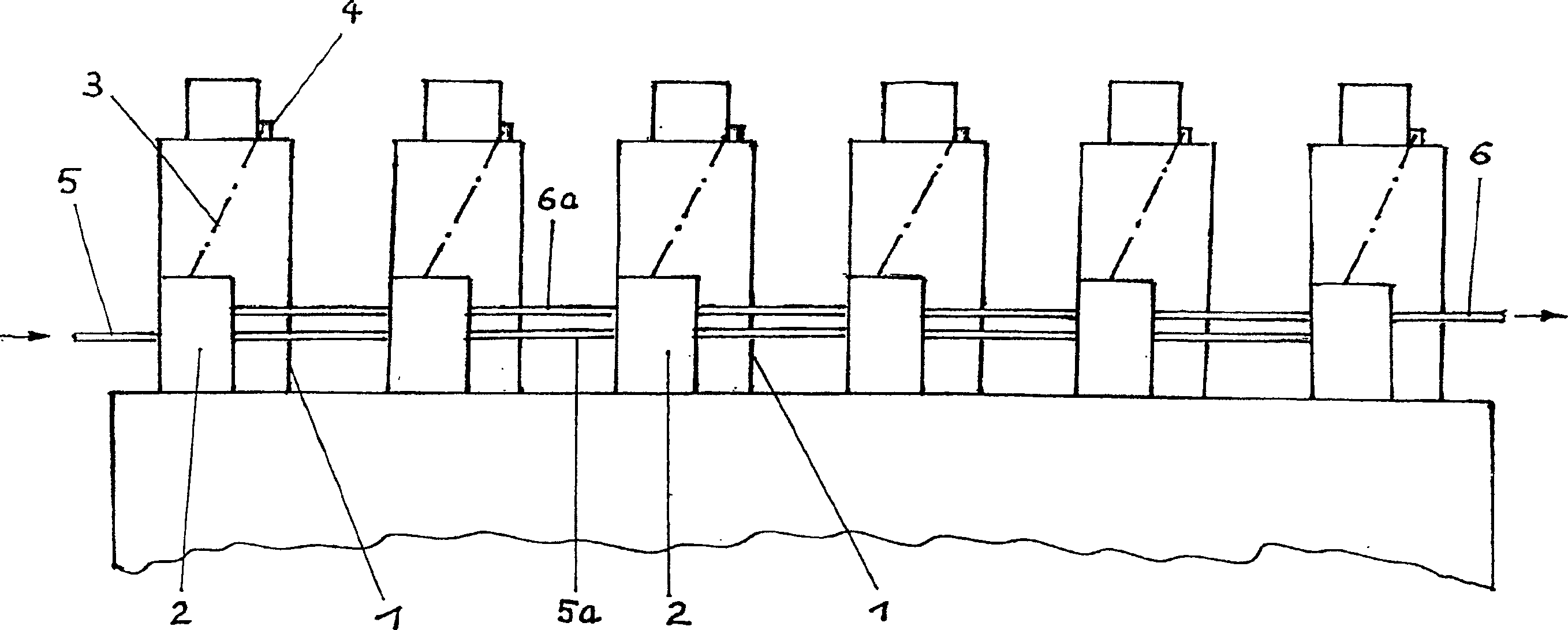
[0016] figure 1 The large diesel engine shown comprises a plurality (here six) of cylinders 1 arranged one behind the other in a row, each of which is associated with an injection pump 2 . The fuel injection pumps 2 assigned to the cylinder 1 are likewise arranged one behind the other. From each fuel injection pump 2 , a fuel injection line 3 leads to at least one respectively associated fuel injector 4 .

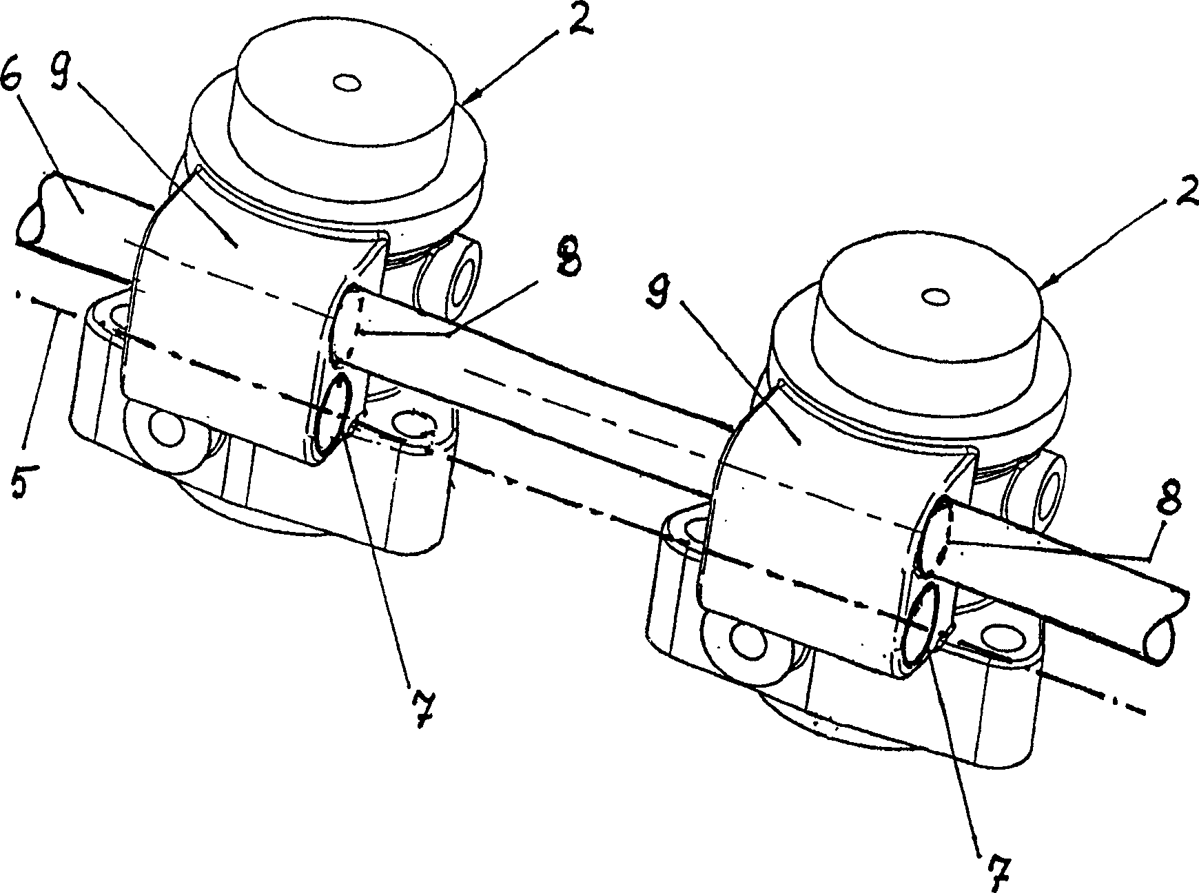
[0017] The fuel injection pumps 2 arranged one behind the other are supplied with fuel via a fuel supply line 5 which runs through the entire pump row. Excess fuel is discharged via a discharge line 6 which also runs through the entire pump train. The fuel supply line 5 originates from...


PUM


Abstract

An engine comprises plural cylinders arranged in a row or more, injection pumps arranged in a row or more, supply and discharge pipes penetrating the injection pump row, and an injection pump housing having an annular containing chamber connected to a pump chamber(12) and connection channels(16,17) vertically arranged and extended radially. The connection channels are communicated with the supply pipe and the discharge pipe. The containing chamber is composed of ring-shaped chambers(14,15) vertically arranged, and the connection channels extended to the discharge pipe and the supply pipe are arranged in the ring-shaped chambers. The circumferences opposed to the connection channels are connected to each other by an over current channel(18).

Description

technical field [0001] The invention relates to an engine, especially a large diesel engine, which has a plurality of cylinders arranged in at least one row in succession and fuel injection pumps associated with the cylinders and arranged in at least one row in succession. At least in some areas, there are continuous and superimposed oil supply lines and oil discharge lines, and the fuel injection pump housings each have a surrounding oil collection chamber structure that can communicate with a pump chamber, thereby leaving radially outwards A plurality of connecting passages stacked one above the other, one of these passages communicates with the oil supply pipeline and one of them communicates with the oil discharge pipeline. Background technique [0002] In this arrangement known to the applicant, the low-pressure oil chamber is formed with an undivided annular space, from which two connecting channels to the oil supply line and the oil discharge line exit. Here, therefo...

Claims


Application Information

Patent Timeline
Patent Type & Authority Applications(China)
IPC IPC(8): F02M37/08F02M39/00F02M39/02F02M53/00F02M55/00F02M59/00F02M59/44F04B17/05F04B53/16
CPCF02M59/44F04B53/16F02M55/00F02M39/02F02M39/00F02M53/00F04B17/05F02M59/442F02M37/08F02M59/00
Inventor H·沙尔M·森根
Owner MAN ENERGY SOLUTIONS SA
Why Eureka
Try Eureka