Sound cavity apparatus

A technology of sound cavity and front sound cavity, applied in the direction of frequency/direction characteristic device, etc., can solve problems such as sharp sound, poor sound playback effect, and influence detection of audio processing chip, etc., to achieve enhanced bass effect, good sound reproduction quality, Sound playback with good sound quality

Inactive Publication Date: 2005-06-01
VIMICRO CORP
View PDF0 Cites 4 Cited by
  • Summary
  • Abstract
  • Description
  • Claims
  • Application Information

AI Technical Summary

Problems solved by technology

However, there is a defect in the existing sound cavity device, that is, the sound sent by this sound cavity device is often sharp, and the sound playback effect will directly affect the sound processing effect of the detection audio processing chip or other music playback circuits.

Method used


Image

  • Sound cavity apparatus
  • Sound cavity apparatus
  • Sound cavity apparatus

Examples


Embodiment 1

[0019] This embodiment is a monophonic structure of the present invention.

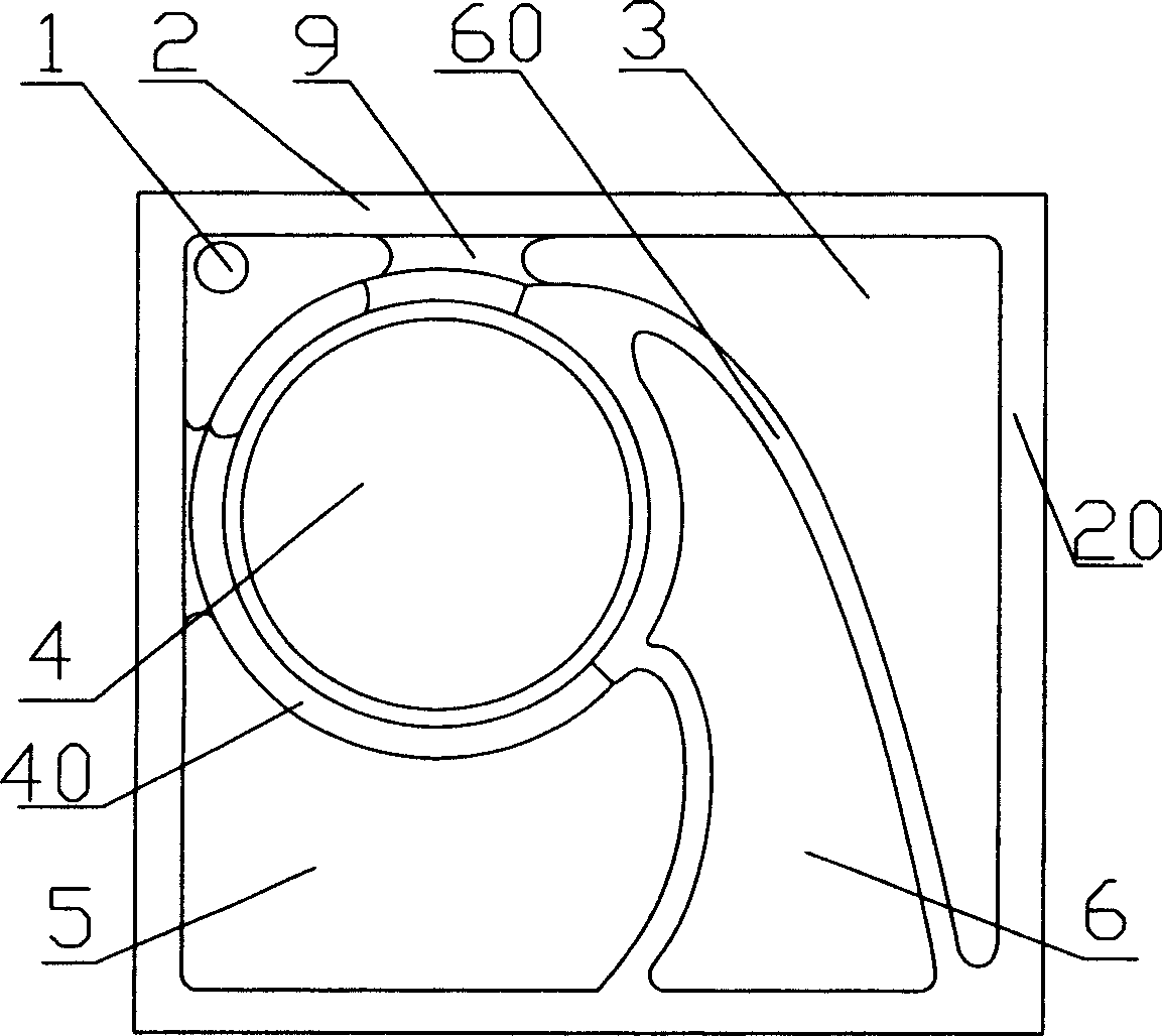
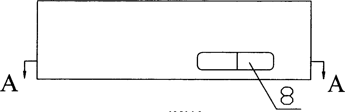
[0020] refer to figure 1 , 2 , 3, a sound cavity device, including the body 2. The body 2 is a cavity structure.

[0021] The main body 2 is provided with a loudspeaker accommodating chamber 4 , a rear sound chamber and a front sound chamber 6 .

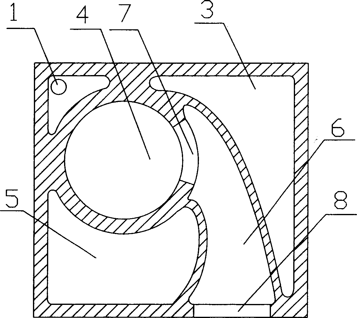
[0022] The speaker accommodating cavity 4 is formed by a cylindrical speaker accommodating cavity side wall 40 vertically arranged on the bottom surface of the body 2, and the height of the speaker accommodating cavity side wall 40 is lower than that of the body 2. The side wall 20 and the side wall 60 of the front sound chamber 6 .

[0023] The front sound chamber 6 is formed by the side wall 60 of the front sound chamber approximately in the shape of "入" and the side wall 20 of the main body 2 .

[0024] A through hole 7 is provided on the side wall shared with the front sound cavity 6 at the bottom of the speaker accommodation cavity 4, so that the s...

Embodiment 2

[0029] The difference between this embodiment and Embodiment 1 is that this embodiment is a two-channel structure, that is, two groups of small sound chambers A and B are symmetrically arranged in the body, and they are all composed of a speaker accommodation chamber, a front sound chamber, and a rear sound chamber. Sound cavity, sound outlet, outlet hole etc. constitute, and its structure is identical with embodiment 1.

[0030] Embodiment 2 can realize 3D sound effects, and is suitable for playing polyphonic music.


PUM


Abstract

The sound cavity device includes one main body, and inside the main body, there are front sound cavity, loudspeaker holding cavity communicated with the front sound cavity and back sound cavity. The main body has also sound exit, through which the front sound cavity is communicated outwards. The front sound cavity is located in the middle of the back sound cavity and has one closed end to form one narrow passage together with one side wall of the main body and to separate the back sound cavity into two communicated parts. Compared with available technology, the present invention has the features of simple and reasonable structure, high sound broadcasting quality, excellent bass effect, etc.

Description

technical field [0001] The invention relates to a sound cavity device used to cooperate with a small loudspeaker to form a sound playing device. technical background [0002] When testing the audio processing chip or other music playing circuits, it is necessary to fix the music playing loudspeaker in the sound cavity device. The existing sound chamber device is composed of an integrally formed body. The body is a cavity, and a speaker accommodating cavity is arranged inside it for accommodating the speaker. A plurality of honeycomb-shaped sound outlet holes are provided on the bottom surface of the speaker accommodating cavity, and the top surface of the speaker accommodating cavity and the inner wall of the body form a rear sound cavity with a relatively large space. When placing the speaker, it is necessary to place the front end of the speaker downward so that the sound can be emitted from the sound hole smoothly. At present, it is generally believed that the rear cav...

Claims


Application Information

Patent Timeline
Patent Type & Authority Applications(China)
IPC IPC(8): H04R1/28
Inventor 陈春亮
Owner VIMICRO CORP
Why Eureka
Try Eureka