Device for producing tubular meshbelt that can be turned inside out

A cylindrical, control device technology used in weaving auxiliary equipment, looms, textiles, etc.

Inactive Publication Date: 2005-06-22
TEXTILMA AG
View PDF2 Cites 4 Cited by
  • Summary
  • Abstract
  • Description
  • Claims
  • Application Information

AI Technical Summary

Problems solved by technology

Its disadvantage is that this fabric either has to be woven as a circular fabric or has two fabric layers connected to each other at least on one side by a selvedge

Method used


Image

  • Device for producing tubular meshbelt that can be turned inside out
  • Device for producing tubular meshbelt that can be turned inside out
  • Device for producing tubular meshbelt that can be turned inside out

Examples


Embodiment Construction

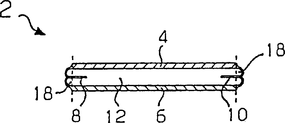
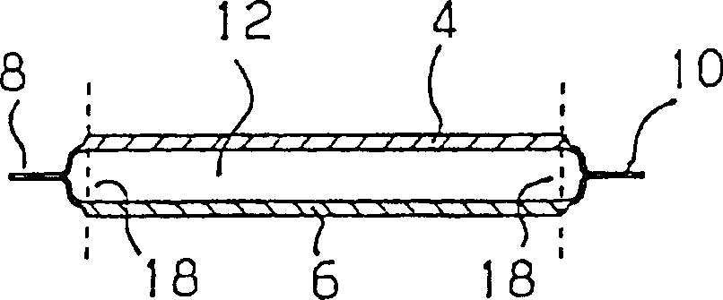
[0025] Figures 1 to 3 A first type of webbing 2 is shown, which consists of an upper fabric layer 4 and a lower fabric layer 6 , which are connected to one another by selvedges 8 and 10 on both sides and form a hollow space 12 between them. In the embodiment shown, the selvedges 8 , 10 run parallel to one another, so that the cavity 12 has the same width over its entire length. figure 2 and 3 The webbing is shown in its unturned state after fabrication; and figure 1 The webbing in is ready for use and will be figure 2 The webbing shown is turned over so that the selvedges 8, 10 are no longer exposed but located inside.

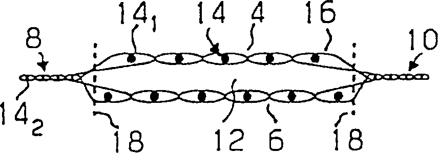
[0026] Such as image 3 As shown, the webbing is woven from warp yarns 14 which are connected to each other by weft yarns 16 . Warp yarn 14 at cavity 12 1 Best warp 14 than selvage 8, 10 2 Has a thicker wire diameter. All warp threads run parallel to each other, with warp thread 14 at selvedges 8, 10 2 Than the warp yarns 14 of the fabric layers 4,...


PUM


Abstract

A device for producing at least two tubular belt bands that are turned inside out, where each of the belt bands has two fabric layers on top of one another and connected to each other in a longitudinal direction by woven hems to form a cavity. Warp threads of the layers have an uniform warp thread density over an entire length of the belt bands. The device includes a power loom having a shedding mechanism with a reed with parallel dents, a weft insertion device extending over an entire width of the power loom, a control unit for controlling the shedding mechanism, and an expander extending over the entire width of the power loom. The expander has a smaller diameter in a tubular area than in a hem area in correspondence with the belt bands to be produced so that clamping pressure of the expander is substantially constant over an entire width of the woven fabric. A thermal cutting device has cutting heads that are operative to cut out the belt bands in the hem area from the woven fabric web.

Description

technical field [0001] The invention relates to a device for producing a hemmable cylindrical webbing according to the preamble of claim 1 . Background technique [0002] PCT Patent International Application Publication No. WO 98 / 51845 describes a cylindrical belt and a device for producing such a cylindrical belt by means of a loom. The loom has a reed whose teeth form a gap that narrows from top to bottom. The reed can be moved up and down, so that the warp threads reach different opening (density) regions, so that a widening cylindrical belt can be produced. For this reason, the fabric must also be guided by the temple (Breithalter) on the two long sides of the fabric and preferably directly after the weft yarn kick-off (Anschlag), and the temple guide can be controlled to increase or decrease the distance from the warp yarn Scaling down is in sync and basically proportional. Such a cylindrical belt can be produced seamlessly in various variations. One of the variants...

Claims


Application Information

Patent Timeline
Patent Type & Authority Applications(China)
IPC IPC(8): D03J1/08D03D1/00D03D3/00D03D11/02D03D41/00D03D47/28D03D47/42
CPCD03D1/0005D03D11/02
Inventor 弗朗西斯科·斯派克
Owner TEXTILMA AG
Why Eureka
Try Eureka