
Building staircase plate prefabricating device

A ladder and staircase technology, applied in the direction of manufacturing tools, ceramic molding machines, molds, etc., can solve the problems of size measurement, affect the appearance, and poor practicability, and achieve the effects of beautiful visual viewing, enhanced utilization, and high practicability.

Active Publication Date: 2019-12-27
湖北宜翔建设有限公司
View PDF5 Cites 2 Cited by
  • Summary
  • Abstract
  • Description
  • Claims
  • Application Information

AI Technical Summary

Problems solved by technology

[0003] However, the following problems will exist in the use of the prefabricated device for building stair treads in the market at present, a. The existing prefabricated stairs all adopt the method of mold pouring to realize the construction of the prefabricated stairs, while the traditional molds all adopt an integrated design. On the one hand, When the traditional casting mold is damaged, it needs to be replaced as a whole, so that the utilization rate of the mold is not high. On the other hand, the one-piece mold design leads to the uniform shape of the prefabricated stairs, and it is impossible to make prefabricated stairs of different sizes, resulting in practicality. Weak; b. The existing prefabricated stairs are all based on the principle of concrete, while the traditional prefabricated device for building stair slabs will accumulate a small amount of concrete on the upper end of the formwork during use, so that the prefabricated stairs will The sides are not flat enough, which affects its appearance, and is also not conducive to the later installation personnel's measurement of the size

Method used


Image

  • Building staircase plate prefabricating device
  • Building staircase plate prefabricating device
  • Building staircase plate prefabricating device

Examples


Embodiment Construction

[0023] In order to make the technical problems, technical solutions and beneficial effects to be solved by the present invention clearer, the present invention will be further described in detail below in conjunction with the accompanying drawings and embodiments. It should be understood that the specific embodiments described here are only used to explain the present invention, not to limit the present invention.

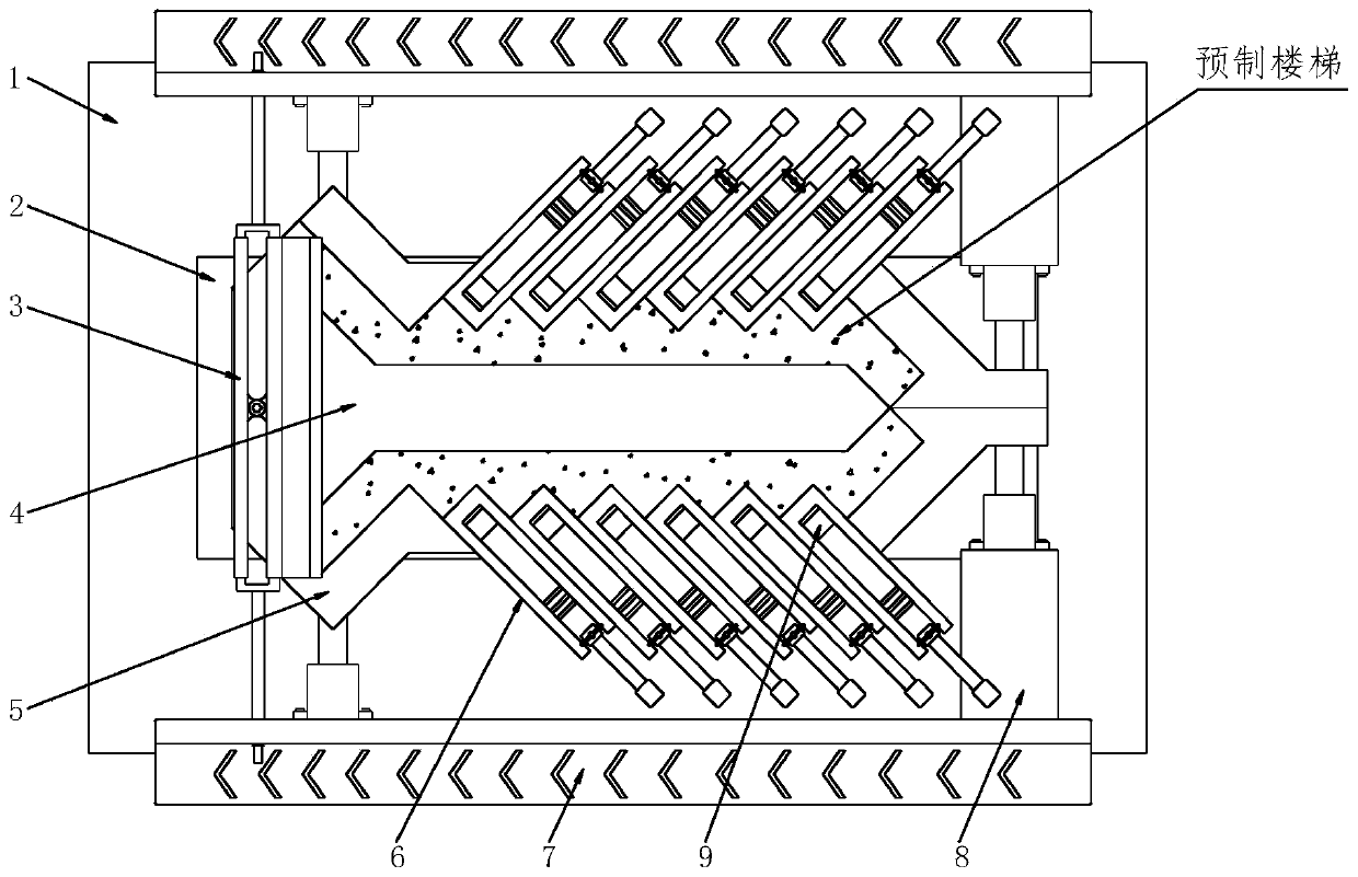
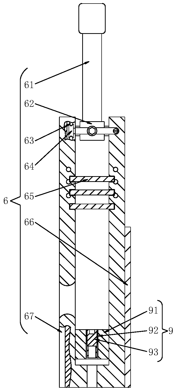
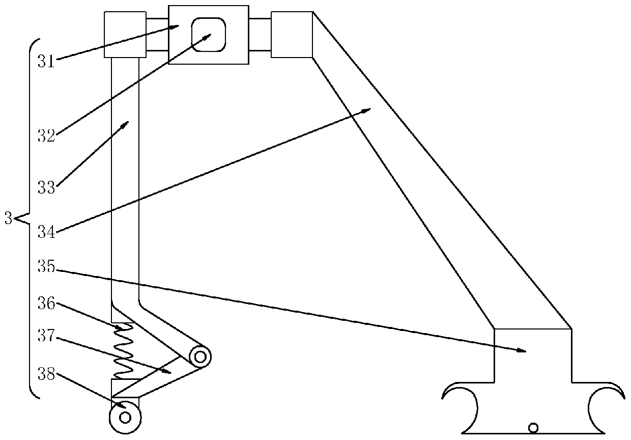
[0024] Referring to 1-5, a prefabricated device for building stair risers is realized by the following technical solutions: a prefabricated device for building stair risers, including a support base 1, a mounting seat 2, a scraping mechanism 3, a first mold 4, The second mold 5, the third mold 6, the operating platform 7, the hydraulic push rod 8 and the positioning mechanism 9, the upper end surface of the support base 1 is welded with the mounting seat 2, and the top center of the mounting seat 2 is welded with the first mold 4 , the top of the first mold 4 is pr...


PUM


Abstract

The invention relates to a building staircase plate prefabricating device. The building staircase plate prefabricating device comprises a supporting base, a mounting base, a scraping and wiping mechanism, a first mold, a second mold, third molds, an operating platform, hydraulic push rods and a positioning mechanism. The mounting base is welded to the upper end surface of the supporting base. Thefirst mold is welded to the center position of the top of the mounting base. The scraping and wiping mechanism is arranged at the top of the first mold. The operating platform is fixed to the upper end surface of the supporting base through bolts. The hydraulic push rods are symmetrically mounted on the side, close to the first mold, of the operating platform. The second mold is connected to the top ends of piston rods of the hydraulic push rods through spot welding. The third molds are sequentially inserted in the middle section of the second mold. U-type grooves are formed in the third molds. Positioning mechanisms are arranged in the U-type grooves. Supporting rods are welded to the end surfaces of the two sides, located on the operating platform, of a connecting and fixing block and are connected with the operating platform. The building staircase plate prefabricating device adopts an insertion-type mold design, and has the characteristics of high utilization rate, high practicability and the like.

Description

technical field [0001] The invention relates to the technical field of prefabricated staircase production, in particular to a prefabricated device for building staircase treads. Background technique [0002] Stairs are components used for vertical communication between floors in buildings. It is used for traffic connection between floors and when the height difference is large. Stairs should also be provided in multi-storey and high-rise buildings with elevators and escalators as the main vertical means of transportation. Although elevators are used as the main vertical means of transportation in high-rise buildings, stairs are still reserved for escape in case of fire. Stairs are composed of continuous rungs, platforms and enclosure components. The prefabricated staircase is a kind of architectural staircase that is produced elsewhere by machinery and then transported to the construction site for splicing. It can perform standardized operations, and the maintenance condi...

Claims


Application Information

Patent Timeline
Patent Type & Authority Applications(China)
IPC IPC(8): B28B1/29B28B7/22
CPCB28B1/29B28B7/225
Inventor 张育军冉红军胡江明
Owner 湖北宜翔建设有限公司
Learn More