Door anti-slamming device

一种设备、门防的技术,应用在门防猛关设备领域,能够解决门防猛关设备不好用、门防猛关设备不能容易地调节需求或改变状态等问题

Active Publication Date: 2017-02-22
尼古拉斯利思霍普金斯
View PDF6 Cites 2 Cited by
  • Summary
  • Abstract
  • Description
  • Claims
  • Application Information

AI Technical Summary

Problems solved by technology

[0013] - Many types of door slam devices are not useful due to the systems employed which prevent a person from closing the door easily at normal speeds
[0014] -Many door slam devices cannot be easily adjusted to suit the user's needs or change state

Method used


Image

  • Door anti-slamming device
  • Door anti-slamming device
  • Door anti-slamming device

Examples


Embodiment 1

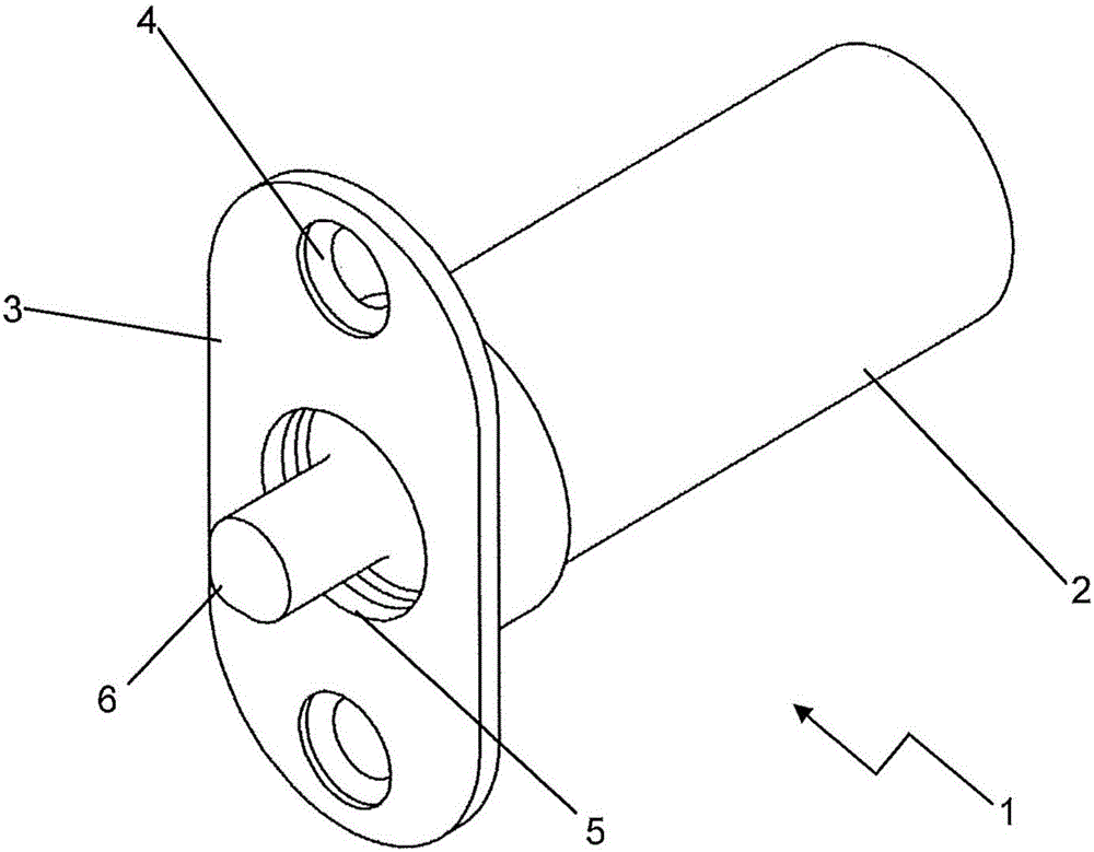
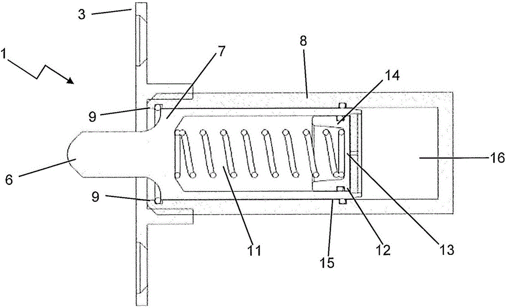
[0205] Figure 2A and 2B An apparatus according to Embodiment 1 of the present invention is shown.

[0206] The device 1 comprises a plunger 7 configured to slide in a chamber 8, also cylindrical. The inlet 5 includes a stop 9 . The head end 6 of the plunger 7 protrudes 18 mm beyond the inlet 5 .

[0207] The plunger 7 comprises a second cavity 10 and biasing means configured as a spring loaded coil 11 . The second cavity 10 is formed by the inner wall of the plunger 7 , the spacer 12 comprising the hole 13 and the movable wall 14 engaging the spring-loaded coil 11 . The plunger 7 and the walls of the chamber 8 comprise O-rings 15 to effectively seal the different parts of the device 1 .

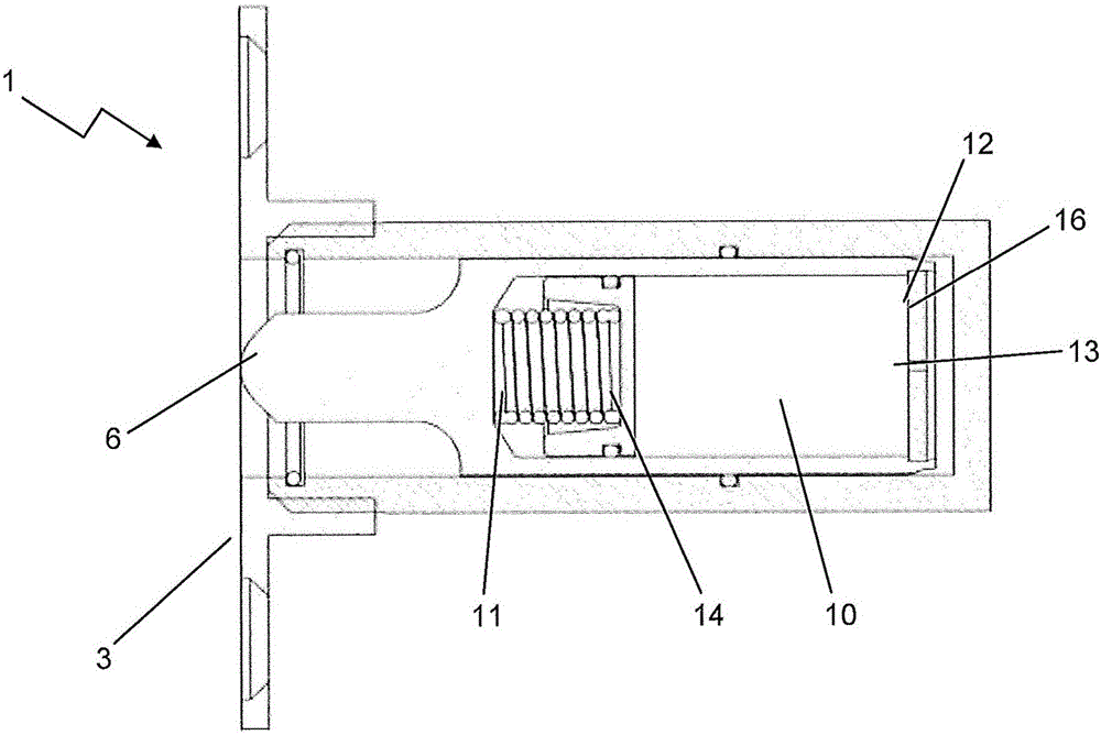
[0208] like Figure 2A As shown, chamber 8 includes a first cavity 16 that is enlarged when the device is in the deployed configuration. In this configuration, the second cavity 10 is contracted. transfer to Figure 2B , the first cavity 16 contracts and the second cavity 10 expands a...

Embodiment 2

[0212] Figure 5A and 5B Each shows the device according to Embodiment 2 of the present invention in an expanded configuration and a compressed configuration.

[0213] In Embodiment 2, through the plunger 7 configured as a concentrated cylinder, the inner wall of the chamber 8 , the spacer 12 containing the hole 13 , and The interaction relationship between the movable walls 14 is used to form the second cavity 10 .

[0214] The biasing means 11 is located in the first cavity 16 and is biased towards the enlarged first cavity 16 . The first cavity 16 is located in the peripheral portion of the chamber 8 remote from the inlet 5 .

[0215] As plunger 7 is pressed into chamber 8, material (not shown) passes through bore 13 and forces moveable wall 14 back to expand the size of second chamber 10 to accommodate movement from first chamber 16. placed materials.

Embodiment 3

[0217] Figure 6A and 6B Each shows a device according to embodiment 3 of the invention in an expanded configuration and a compressed configuration.

[0218] In embodiment 3, the spacer 12 is a fixed wall integrated into the chamber 8 , wherein the spacer 12 comprises a hole 13 comprising a nozzle 20 .

[0219] The second cavity 10 is located on the opposite side of the partition 12 and away from the inlet 5 . A second cavity 10 is delimited by the inner wall of the chamber 8 , the spacer 12 and the movable wall 14 biased towards the spacer 12 by the spring-loaded coil 11 .

[0220] The first cavity 16 is located on the side of the spacer 12 opposite the second cavity 10 and close to the inlet 5 and is defined by the inner wall of the chamber 8 , the spacer 12 of the receiving hole 13 and the front surface 21 of the plunger 7 .

[0221] The plunger 7 is a solid cylindrical member forced into the first cavity 16 .

[0222] It should be understood that aspects of any of Emb...


PUM


Abstract

A door anti-slamming device, wherein the device includes a chamber with an entrance located at a first end; wherein the chamber houses a plunger component with a tip configured to slidably move in and out of the entrance, therefore defining a compacted configuration and an extended configuration of the device, respectively; wherein the device includes an biasing means configured to bias the device towards the extended configuration; wherein the device includes a first cavity and a second cavity located within the chamber and / or plunger component, and wherein a partition is located between the first and second cavity characterised in that the partition includes an orifice configured to control material transfer rate between the first cavity and second cavity, wherein the device is configured to transition to the compacted configuration at a rate controlled by the material transfer from the first cavity into the second cavity.

Description

technical field [0001] The invention relates to a door slam-closing prevention device and a using method thereof. Background technique [0002] There are a wide variety of industries and installations that can benefit from door slam protection. This benefits from the safety aspect as well as the comfort aspect of preventing injuries from accidental slamming of the door and avoiding damage to the door or surrounding structure. [0003] For example, the doors of shipping containers are very heavy and bulky. At sea, or even in port, even if personnel or security agencies try to temporarily hold the door in place, the wind can carry the door and cause it to slam against the tank wall or the entrance quickly. This applies in particular during inspections of containers by customs services, which usually take place at sea or during loading and unloading. If a person is inadvertently in the path of the door as the door slams against the surface, that person could be seriously inj...

Claims


Application Information

Patent Timeline
Patent Type & Authority Applications(China)
IPC IPC(8): E05F5/06E05F5/02
CPCE05F5/02E05F5/08E05F5/10
Inventor 尼古拉斯·利思·霍普金斯
Owner 尼古拉斯利思霍普金斯
Why Eureka
Try Eureka