Engine flow resistance testing device and testing method thereof

A test device and engine technology, applied in the direction of engine test, measurement device, machine/structural component test, etc., can solve problems such as implementation difficulties, engine oil leakage, and engine scrapping, so as to achieve no hidden safety hazards and convenient safety hazards. Effect

Pending Publication Date: 2018-05-08
JIANGXI TENHLE POWER CO LTD
View PDF0 Cites 5 Cited by
  • Summary
  • Abstract
  • Description
  • Claims
  • Application Information

AI Technical Summary

Problems solved by technology

[0003] The previous method is to only monitor the oil pressure, not the flow rate, because the performance requirements of the equipment cannot be met, and the engine flow path needs to be changed, so it is difficult to realize
Therefore, the existing engine oil pressure test has the actual problem that the test cannot reflect the full branch flow resistance of the engine
And when using sensor to test the performance of engine in the prior art, mostly need punching on the engine, there is potential safety hazard in punching on the engine, if the position of punching is chosen badly may make engine oil leak, more serious meeting lead to engine failure

Method used


Image

  • Engine flow resistance testing device and testing method thereof
  • Engine flow resistance testing device and testing method thereof
  • Engine flow resistance testing device and testing method thereof

Examples


Embodiment Construction

[0025] In the present invention, it should be understood that the terms "length", "width", "upper", "lower", "front", "rear", "left", "right", "vertical", "horizontal" ", "top", "bottom", "inner", "outer", "clockwise", "counterclockwise", "axial", "radial", "circumferential", etc. indicated the orientation or position relationship is based on The orientation or positional relationship shown in the drawings is only for the convenience of describing the present invention and simplifying the description, rather than indicating or implying that the indicated device or element must have a specific orientation, be constructed and operated in a specific orientation, and therefore should not be construed as Limitations of the present invention.

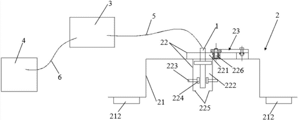
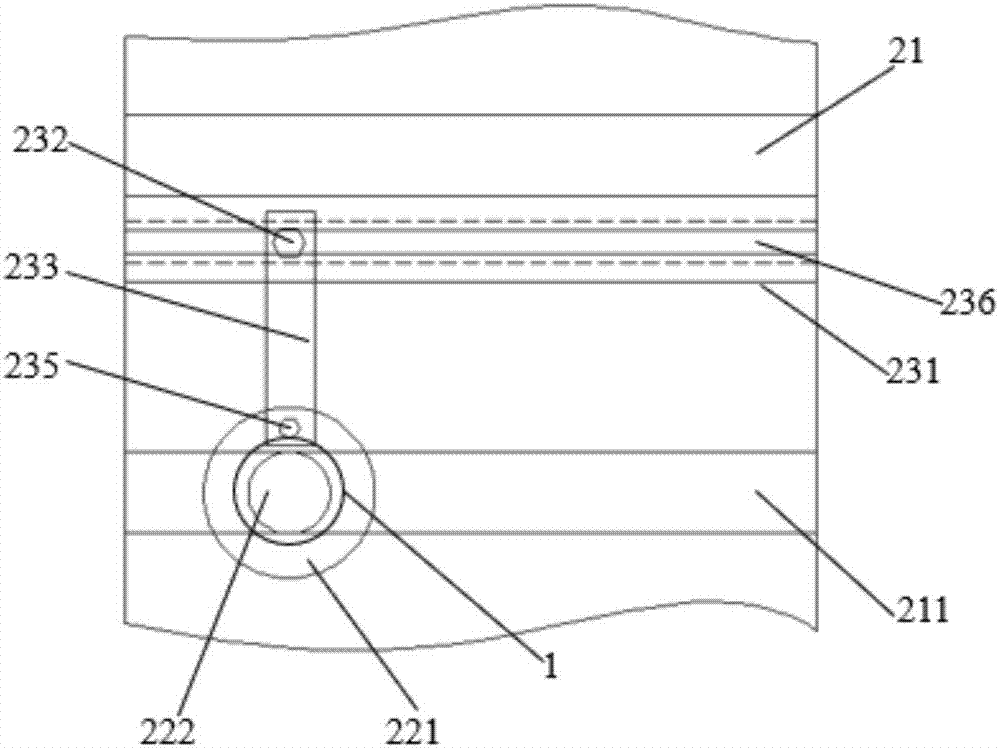
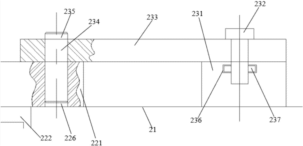
[0026] like figure 1 , figure 2 , image 3 As shown, an engine flow resistance test device includes an ultrasonic flow sensor 1, an installation mechanism 2 for installing the ultrasonic flow sensor 1 on the engine, a processor 3 for proc...


PUM


Abstract

The invention discloses an engine flow resistance testing device and a testing method thereof. The engine flow resistance testing device comprises an ultrasonic wave flow sensor, a mounting mechanismfor mounting the ultrasonic wave flow sensor on an engine, a processor for processing acquired information, and a display device. The ultrasonic wave flow sensor is connected with the processor through a data wire I. The processor is connected with the display device through a data wire II. The mounting mechanism comprises a mounting bracket, a sensor mounting chamber and a fixing mechanism. The sensor mounting chamber is connected with the mounting bracket. The ultrasonic wave flow sensor is mounted in the sensor mounting chamber. The fixing mechanism is arranged on the mounting bracket. Themounting bracket is provided with a track. A mounting chamber I is slidably connected with the track. The whole sensor mounting chamber can move along the track. The ultrasonic wave flow sensor can befinely adjusted in a horizontal plane. The testing device and the testing method according to the invention are used for testing the flow of each oil duct of the engine, thereby substantially understanding true data of each oil duct flow resistance (namely oil consumption) and performance of the engine.

Description

technical field [0001] The invention belongs to the technical field of engine performance testing, and particularly relates to an engine flow resistance testing device and a testing method. Background technique [0002] During the engine bench test, various data need to be monitored, and the flow resistance in the entire lubrication system needs to be tested when the lubrication efficiency of the lubrication system is tested. [0003] The previous method is to monitor only the oil pressure and not the flow, because the performance requirements of the equipment cannot be met, and the engine flow path needs to be changed, so it is difficult to achieve. Therefore, the existing oil pressure test has the actual problem that the test cannot reflect the flow resistance of the whole engine branch. Moreover, when using sensors to test the performance of the engine in the prior art, most of the holes need to be drilled on the engine, which has potential safety hazards. If the locatio...

Claims


Application Information

Patent Timeline
Patent Type & Authority Applications(China)
IPC IPC(8): G01M10/00G01M15/02
CPCG01M10/00G01M15/02
Inventor 李阳星张宝秀何一太邱鹏陈建伟杨新月
Owner JIANGXI TENHLE POWER CO LTD
Why Eureka
Try Eureka