Unlock instant, AI-driven research and patent intelligence for your innovation.

Flow regulating valve, flow rate measuring device, flow control device, and flow rate measuring method

A technology of flow control device and flow control valve, which is applied in the direction of using electric device flow control, flow control, measurement flow/mass flow, etc. Made into compact and other issues

Inactive Publication Date: 2005-06-22
TOYO VALVE
View PDF0 Cites 6 Cited by
  • Summary
  • Abstract
  • Description
  • Claims
  • Application Information

AI Technical Summary

Problems solved by technology

However, there is still another problem, that is, there is a limit to the range of flow rates due to the diameter of the hole
In addition, at the pressure measurement point on the downstream side, the turbulence of the fluid generated after the fluid passes through the hole makes the data unstable, and, more specifically, when the pressure difference is high, the detection Data instability is further strengthened
In the worst case, the assay itself may become impossible
In addition, since the orifice flow rate must have two pressure detecting parts on the upstream side and the downstream side, there is a problem that the structure for measuring the flow rate cannot be made compact.

Method used


Image

  • Flow regulating valve, flow rate measuring device, flow control device, and flow rate measuring method
  • Flow regulating valve, flow rate measuring device, flow control device, and flow rate measuring method
  • Flow regulating valve, flow rate measuring device, flow control device, and flow rate measuring method

Examples


Embodiment Construction

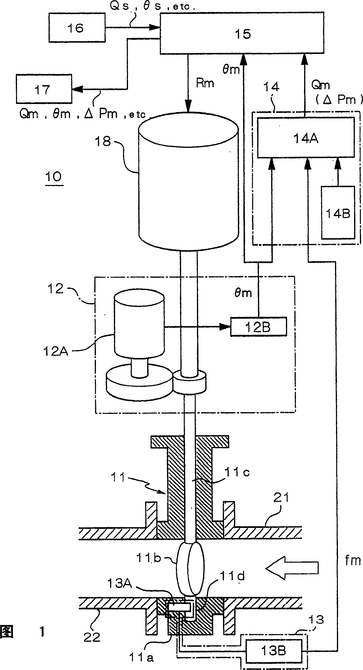
[0032] Embodiments of the flow regulating valve, the flow velocity measurement device, the flow control device, and the flow velocity measurement method of the present invention will be described in detail below with reference to the accompanying drawings. The "flow regulating valve" mentioned in the present invention is based on a functional concept, and thus includes all valves having a structure capable of regulating a flow rate. Therefore, the flow regulating valve is not limited to a valve generally used for the purpose of regulating a flow rate.

[0033] In carrying out the present invention, the force component in the fluid passage direction of the load exerted by the fluid on the valve member of the flow regulating valve (hereinafter simply referred to as "stress") is detected. The detection of stress can be based on the method that the detector directly detects the stress applied to the valve part, and is used to detect the relative displacement of the valve part (for...


PUM


Abstract

A fluid regulating valve (11), which has a valve disc (11b), is operably placed in a fluid passage, and can adjust the flow rate of liquid according to the valve opening of the valve disc (11b), characterized in that it includes a A stress detection device (13) for the component of the force in the direction of the fluid passage of the load exerted by the fluid on the valve disk, and a valve opening degree detection device (12) for detecting the opening degree of the valve disk, the flow rate A calculation means (14) calculates a flow velocity (Qm) based on the stress (fm) obtained by the stress detection means, and the valve opening degree (θm) obtained by the valve opening degree detection means. The valve disc drive means (18) are controlled by the control means (15) in accordance with said flow rate in order to open and close the valve disc. This enables the flow rate to be calculated with higher sensitivity and accuracy than the prior art, the structure is compact and simple, and it provides stable data.

Description

technical field [0001] The present invention relates to a flow control valve, a flow velocity measurement device, a flow control device, and a flow velocity measurement method, in particular to a flow velocity measurement technique or a flow control technique, and butterfly valves are preferably used in these techniques. Background technique [0002] In general, butterfly valves are known in which a plate-like valve member, which is formed rotatably relative to its housing, rotates about an axis substantially perpendicular to the direction of the fluid passage. The butterfly valve is manufactured so that it can control its flow rate through the valve opening of the valve member. [0003] A method of measuring a flow rate and a method of controlling a flow rate using the butterfly valve are disclosed in Unexamined Japanese Patent Publication No. Hei-7-174596. In said document, it is disclosed that the dynamic torque of a valve member of the butterfly valve is detected, and t...

Claims


Application Information

Patent Timeline
Patent Type & Authority Applications(China)
IPC IPC(8): G01F1/00G01F1/26G01F1/28G01F1/42G05D7/06
CPCG01F1/26G01F1/28G05D7/0635Y10T137/7759G05D7/06
Inventor 田中利暖一濑忠治矢田胜久
Owner TOYO VALVE