Supercharge Your Innovation With Domain-Expert AI Agents!

Torque converters

A converter and torque technology, applied in the field of mechanical devices, can solve the problems of power consumption, power reduction, and limited effect.

Inactive Publication Date: 2005-07-27
徐洪德
View PDF0 Cites 1 Cited by
  • Summary
  • Abstract
  • Description
  • Claims
  • Application Information

AI Technical Summary

Problems solved by technology

These media parts are indispensable, but it inevitably consumes part of the power at the same time, thus reducing the power
The traditional approach is to use different structures, materials or different lubrication methods to reduce this part of the loss and improve mechanical efficiency. Although efforts have been made, the results are limited and the loss is more or less inevitable.

Method used


Image

  • Torque converters
  • Torque converters

Examples


Embodiment Construction

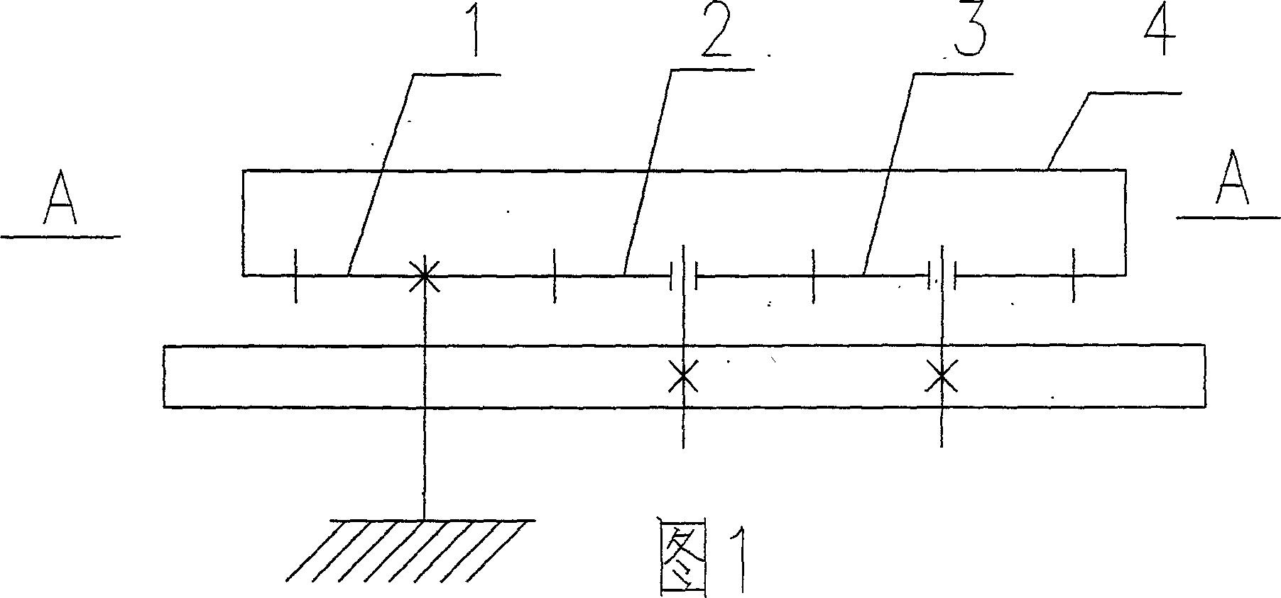
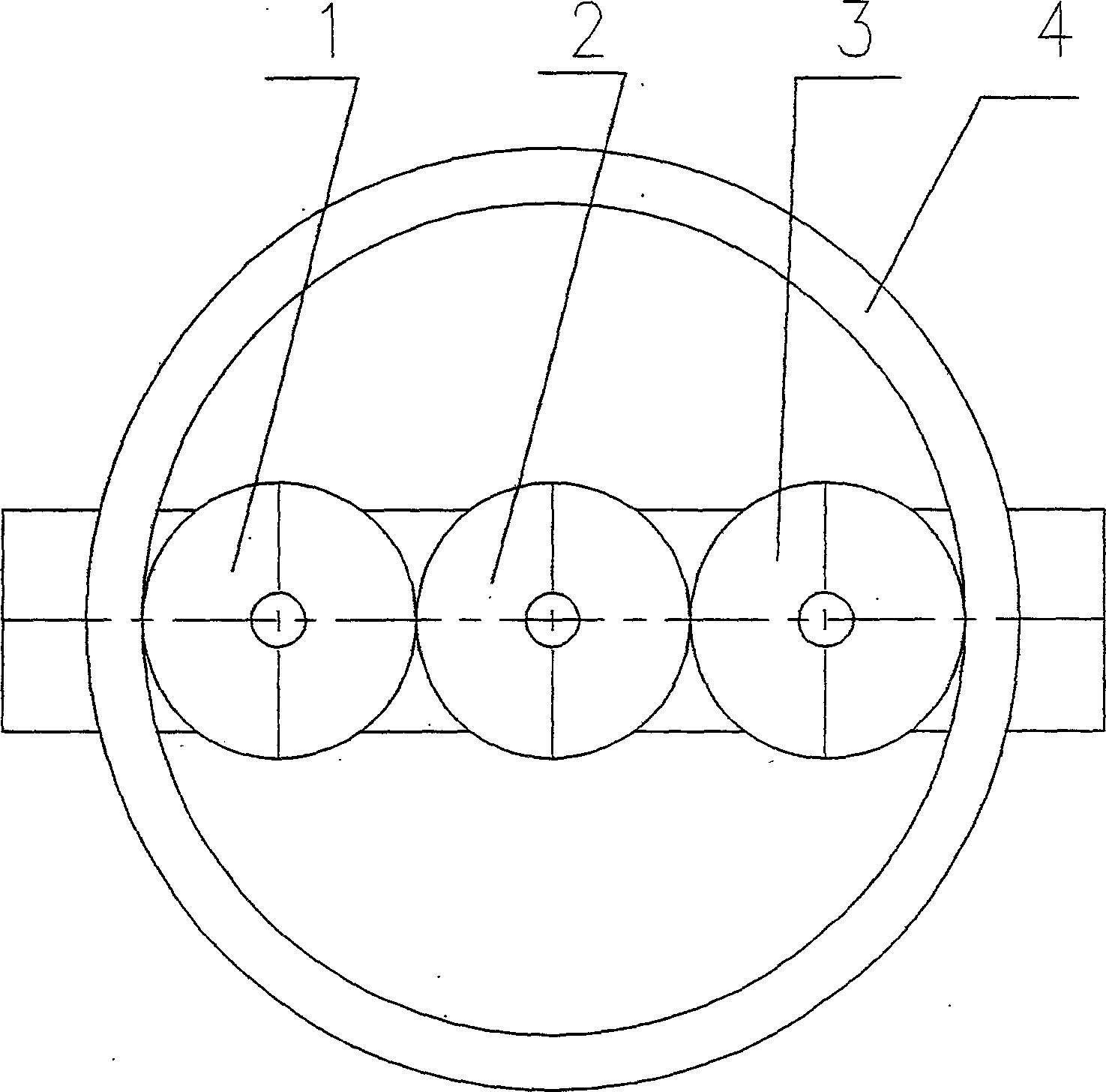
[0010] Embodiments of the present invention will be described below with reference to the drawings.

[0011] When the resistance is applied at the meshing point of the 4th gear and the 3rd gear of the 4th gear, the 4th gear exerts resistance to the pin of the 3rd gear through the 3rd gear, because the meshing point of the 4th gear and the 3rd gear is to the central shaft The distance is 5R (assuming that the radii of No. 1, No. 2 and No. 3 gears are all R), and the distance from the pin of No. 3 gear to the central axis is 4R, so the resistance moment formed on the gear bracket is 4 / 5, and Not 1. As for the junction of the pin of the No. 2 gear and the gear bracket, because the pin of the No. 2 gear is 2R away from the central axis, it receives a force from the No. 3 gear and a reaction force from the No. 1 gear. The two forces and The reverse moment caused by 2R is 4 / 5; due to the reaction force of No. 2 gear to No. 3 gear, the moment caused by the junction of No. 3 gear pin...


PUM


Abstract

Moment of force transformation unit is a mechanical device, consisting of one internal gear, one sun gear, and two planetary gears, which are geared each other. Besides the routine function of fulcrum, the effect of gear connection point as fulcrum with rotation surrounding the sun gear make the moment of force transform, then achieve the energy saving purpose.

Description

technical field [0001] The invention is a mechanical device that transmits driving force through rotation. Background technique [0002] Usually, the device that transmits the driving force by rotation uses transmission shafts, gears, levers and other components to transmit the driving force generated by the power source to the working part to counter the resistance and achieve the desired purpose. These media parts are indispensable, but it inevitably consumes part of the power at the same time, thereby reducing the power. The traditional approach is to use different structures, materials or different lubrication methods to reduce this part of the loss and improve mechanical efficiency. Although efforts have been made, the results are limited and the loss is more or less inevitable. [0003] The present invention is made in view of the problems in the prior art. The purpose is to minimize this part of the lost power in order to achieve the effect of saving energy. Conte...

Claims


Application Information

Patent Timeline
IPC IPC(8): F16H1/32F16H1/46
CPCF16H1/32
Inventor 徐洪德
Owner 徐洪德
Features
  • R&D
  • Intellectual Property
  • Life Sciences
  • Materials
  • Tech Scout
  • Unparalleled Data Quality
  • Higher Quality Content
  • 60% Fewer Hallucinations
Learn More