Electrical switch

An electrical switch and switch technology, applied in electrical switches, electrical components, exhaust and other directions, can solve problems such as increasing device damage and limiting comfort.

An electrical switch and switch technology, applied in electrical switches, electrical components, exhaust and other directions, can solve problems such as increasing device damage and limiting comfort.

CN1666308AInactive Publication Date: 2005-09-07KONINKLIJKE PHILIPS ELECTRONICS NV

Image

  • Electrical switch
  • Electrical switch
  • Electrical switch

Examples


Embodiment Construction

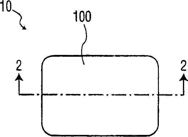
[0017] With reference to the accompanying drawings, especially figure 1 , which shows an improved switch generally indicated by reference numeral 10 in accordance with the present invention. Switch 10 is a single pole switch having a generally rectangular shape. However, other shapes including circles or squares may be used for the switch 10 .

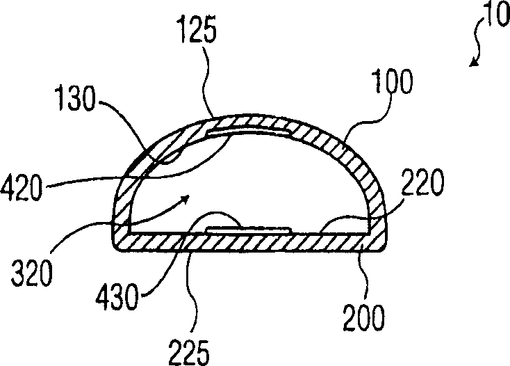
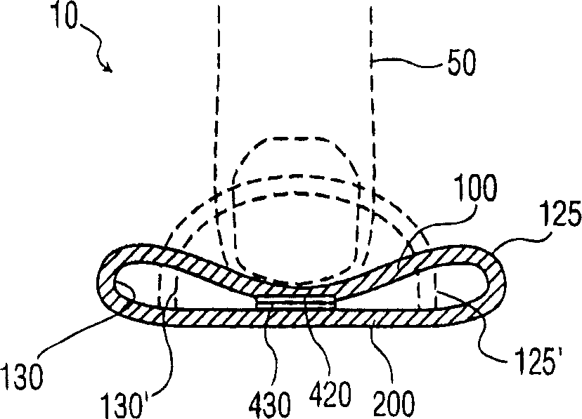
[0018] refer to figure 1 with 2 , the switch 10 has an upper layer 100 and a lower layer 200 . The upper layer 100 and the lower layer 200 are made of a soft flexible material such as silicone. The flexibility of the upper layer 100 and the lower layer 200 prevents damage when the switch 10 is used as a wearable electronic device. Furthermore, the flexibility of the upper layer 100 and the lower layer 200 provides comfort to the wearer when the switch 10 is used as a wearable electronic device. Preferably, the upper layer 100 and the lower layer 200 are made of airtight material. More preferably, the upper layer 100 and the lowe...


PUM


Abstract

There is provided a switch having a flexible upper member, that is substantially electrically non-conductive, having an inner surface with an upper contact area that is electrically conductive and connected to a circuit, and a lower member that is substantially electrically non-conductive, having an inner surface with a lower contact area that is electrically conductive and connected to the circuit, wherein the upper member and the lower member are sealingly connected to form a chamber therebetween, the upper contact area and the lower contact area are separated by at least a portion of the chamber and a force applied to the upper member causes the upper contact area and the lower contact area to make contact and close the switch of the circuit.

Description

technical field [0001] The invention relates to an electric switch, in particular to a flexible air cushion type electric switch. Background technique [0002] The use of electrical switches for closing electrical circuits is known. Such switches include substantially rigid mechanical devices for selectively connecting conductive areas to complete an electrical circuit. Additionally, conductive fibers in various quilted or woven fabrics are also known for use as conductive traces, biosensors, electrodes, and other wearable electronics. These wearable electronics typically require switches to operate. A disadvantage of existing switches is the rigidity of the device attached to the flexible wearable electronics. This rigidity limits the comfort of the wearer of the wearable electronic device and also increases the likelihood of device damage due to breakage. Therefore, there is a need to provide a flexible electrical switch that does not have the above disadvantages. Pre...

Claims


Application Information

Patent Timeline
07 Sep 2005
Publication
CN1666308A
IPC
H01H13/52; H01H3/00; H01H3/14; H01H13/702
CPC
H01H13/702; H01H3/142; H01H2223/062; H01H2209/074; H01H2213/01
Inventors
G·马马罗波洛斯; C·阿范希尔登