
Cornice system

A panel and front panel technology, applied in construction, curtain shielding, window decorations, etc., can solve problems such as failure to achieve beneficial properties

Inactive Publication Date: 2005-11-02
JUNE TAILOR
View PDF0 Cites 0 Cited by
  • Summary
  • Abstract
  • Description
  • Claims
  • Application Information

AI Technical Summary

Problems solved by technology

However, such cornices do not achieve certain beneficial properties (and / or combinations of properties)

Method used


Image

  • Cornice system
  • Cornice system
  • Cornice system

Examples


Embodiment Construction

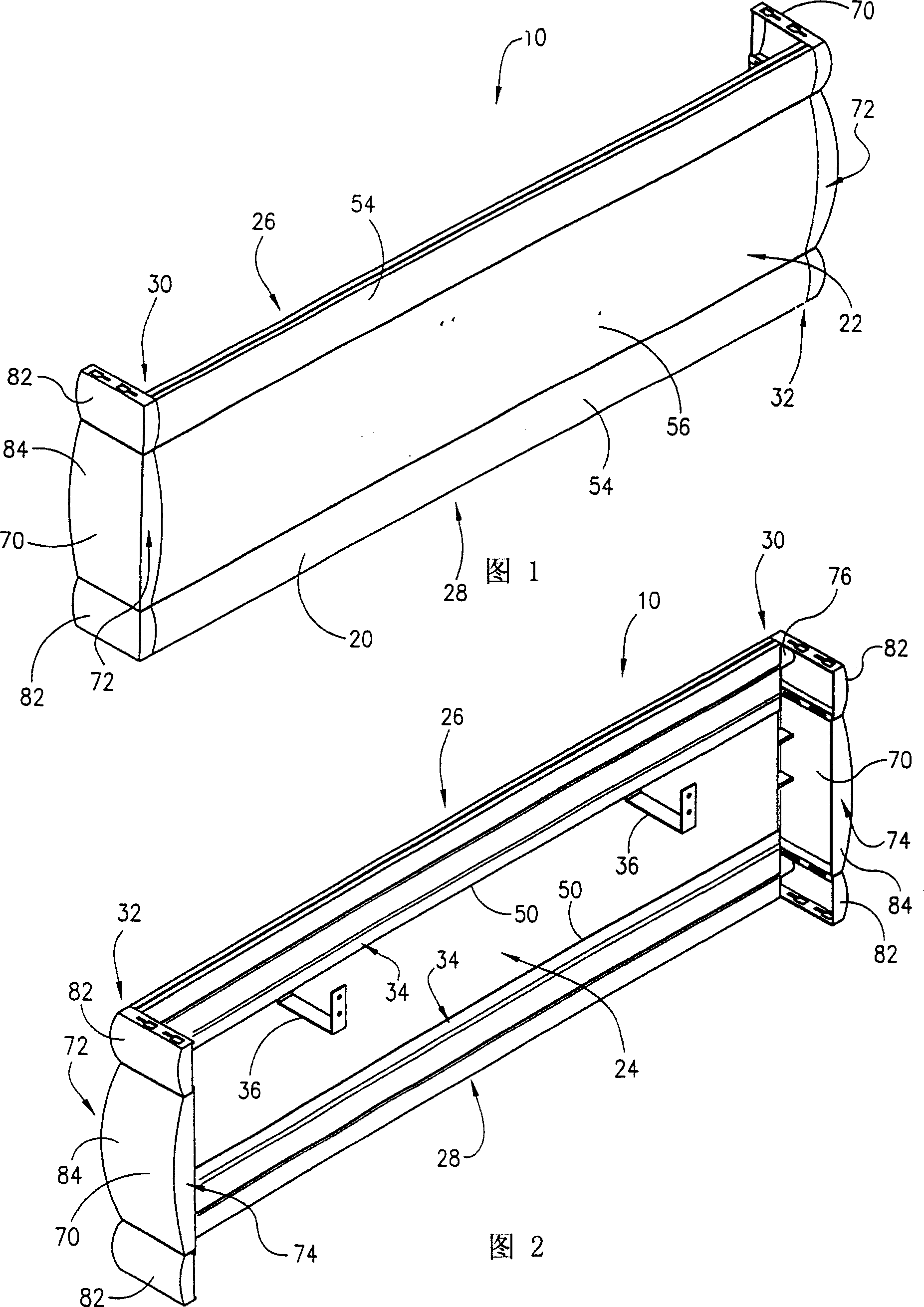
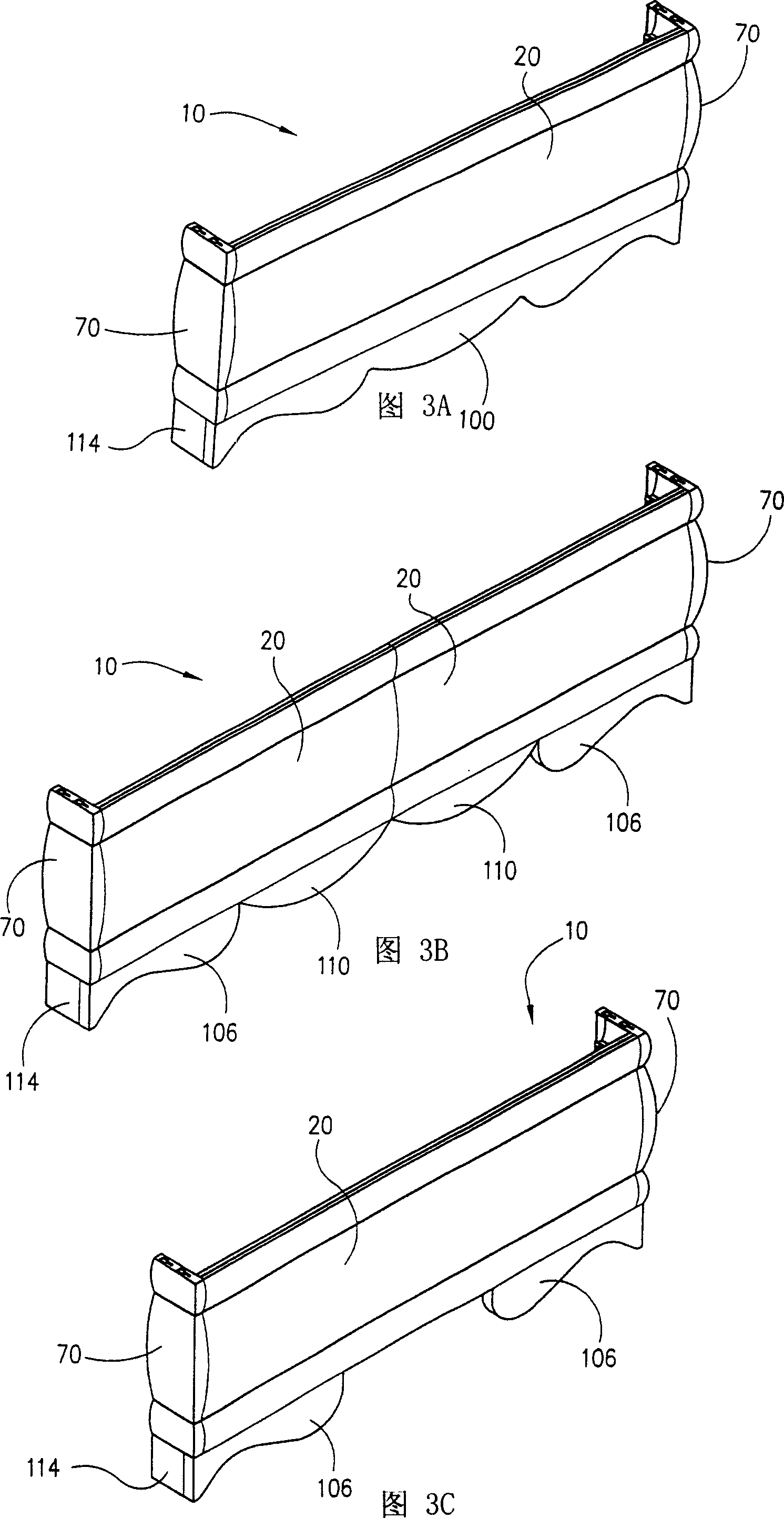
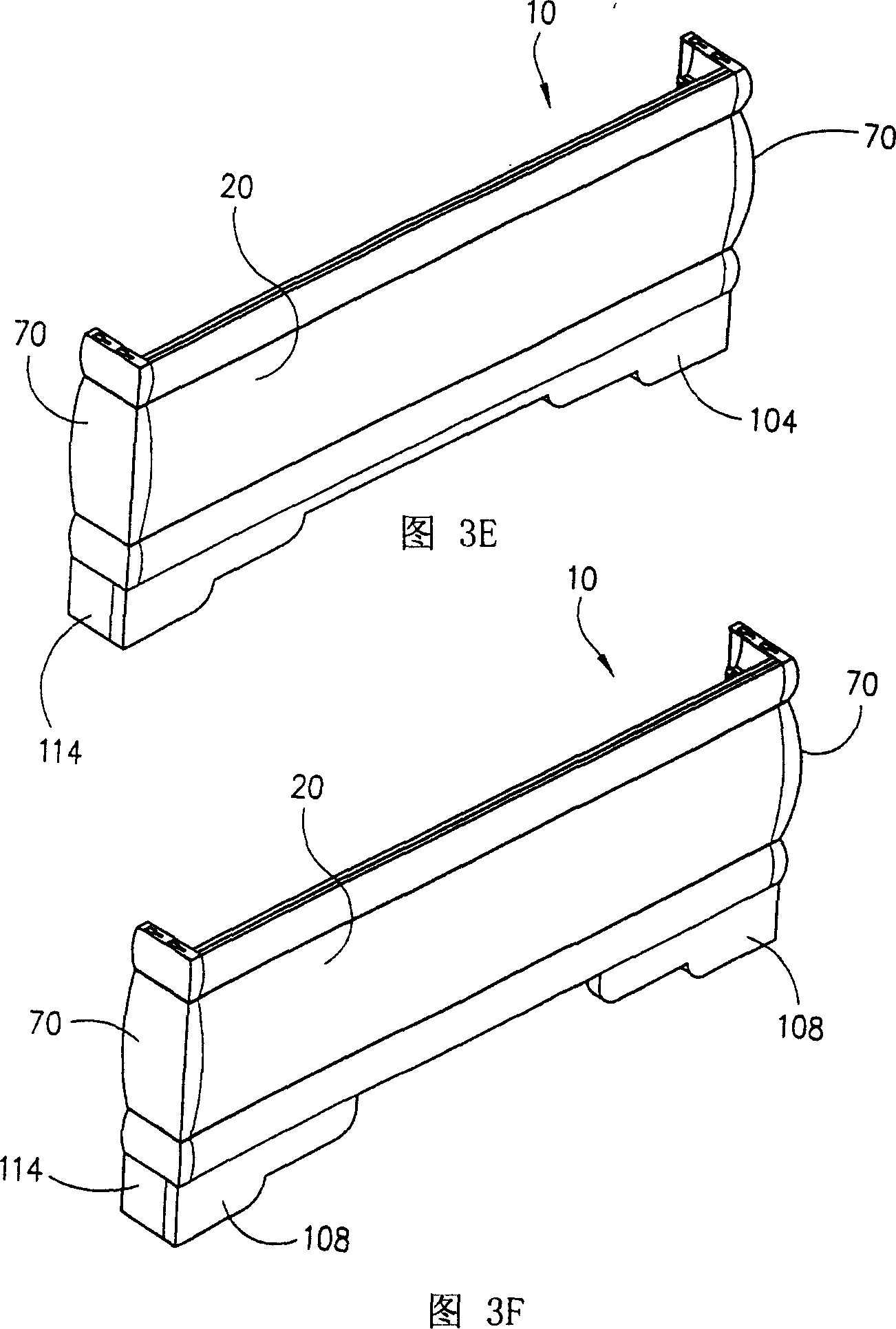
[0038] According to any of the exemplary embodiments, the cornice system can be configured for various decorative or ancillary uses (eg, window casings, cornices, decorative drapes, trim, frames, headboards, etc.). The cornice system can also be used with other accessories, such as a separate window ornament, or as part of a window ornament by attaching appliques, cutouts, or other accessories that are configured to hang (or otherwise support) on cornice systems and / or to apply covering materials such as paint, stain, wallpaper, textile, cloth or other trim, scenery or decoration.

[0039] With reference to the drawings, according to any exemplary embodiment, the cornice system provides a standard form structure formed of different components (shown schematically as sections or segments with one or more front profiles and return profiles), The components are relatively rigid and can be assembled into various configurations. Parts can be made of different materials and have di...


PUM


Abstract

A modular cornice system includes at least one substantially rigid face section and at least one substantially rigid return section having a connector configured to couple the return section and the face section. The system further includes at least one retainer on the face section configured to engage a bracket for attaching the cornice system to a mounting surface. An opening may be provided on the sections to receive a portion of a cover material, so that the cover material may be applied over at least a portion of the face section.

Description

[0001] Cross References to Related Applications [0002] Pursuant to U.S.C. 35 §119(e)(1), this application claims priority to U.S. Provisional Application No. 60 / 464,509, filed April 22, 2003, and entitled "Eavesboard Systems" (the The entire content is used by reference in this application). technical field [0003] The invention relates to a cornice system. More particularly it relates to a system for using decorations, such as covering materials. The invention relates more particularly to a system having a standard form. More particularly, the present invention relates to a system that can be easily assembled into various configurations by the user. Background technique [0004] As is well known, cornices may be used within a space (eg, room, etc.) for decorative purposes or uses, such as fitting window treatments or concealing window hardware such as curtain rods. Known cornices are generally formed from a wooden base to which batting or the like is attached to form...

Claims


Application Information

Patent Timeline
Patent Type & Authority Applications(China)
IPC IPC(8): E04F19/00
Inventor 伊莱娜·A·雷普弗朗西斯·A·约格斯特
Owner JUNE TAILOR
Learn More