Check patentability & draft patents in minutes with Patsnap Eureka AI!

Thermosensitive head

A technology of thermal head and heating resistor, applied in the field of thermal head, can solve problems such as difficulty in reducing uneven printing density, inability to ensure expansion of common electrode area, complex external energy control, etc., so that printing density unevenness is not obvious Effect

Inactive Publication Date: 2005-12-14
ALPS ALPINE CO LTD
View PDF2 Cites 1 Cited by
  • Summary
  • Abstract
  • Description
  • Claims
  • Application Information

AI Technical Summary

Problems solved by technology

[0006] However, the miniaturization of the (thermal) head and the increase in the area of ​​the common electrode are opposite. If the miniaturization of the head is to be realized, the expansion of the area of ​​the common electrode cannot be ensured. On the contrary, if the area of ​​the common electrode is increased, then ( Thermal) head will be enlarged
Therefore, the common resistance cannot be reduced, and it is difficult to reduce the printing density unevenness caused by the common voltage drop
To make the calorific value of each printed dot uniform, such as described in Patent Documents 1 and 2, it is necessary to adjust the resistance value of the conductive circuit, or to perform complicated external energy control.

Method used


Image

  • Thermosensitive head
  • Thermosensitive head
  • Thermosensitive head

Examples


Embodiment Construction

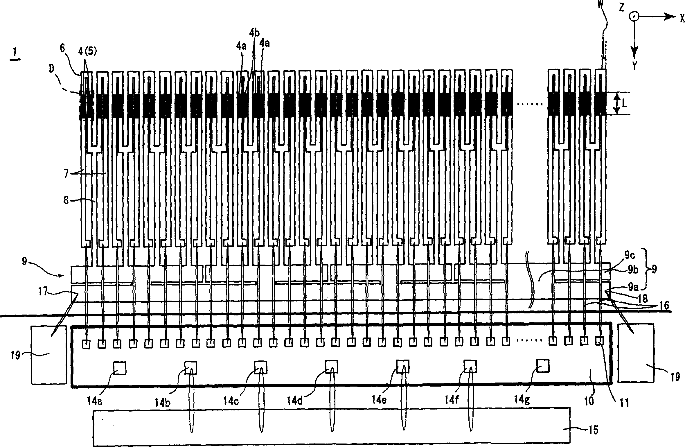
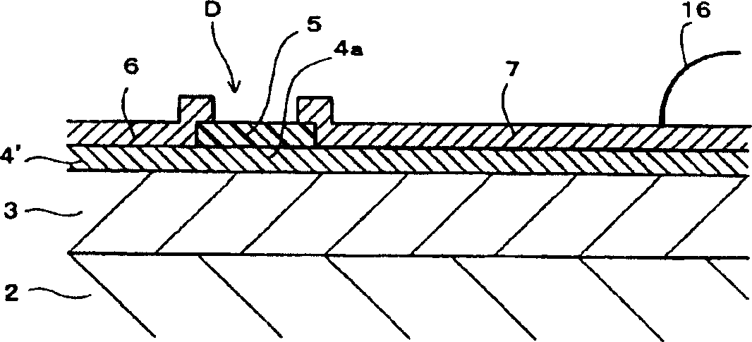
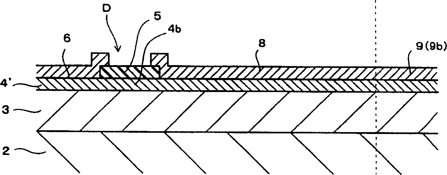
[0024] Figure 1 to Figure 3 A thermal head 1 according to an embodiment of the present invention is shown. In each figure, the X direction is the arrangement direction of the printed dots (and the extension direction (longitudinal direction) of the common line), the Y direction is the energization direction of the printed dots (and the width direction of the common line), and the Z direction is the thermal The stacking direction of each layer of the sensitive head.

[0025] The thermal head 1 has a heat storage layer 3 formed of, for example, a heat insulating material such as glass, on a substrate 2 made of Si, a ceramic material, a metal material, or the like, which is excellent in heat dissipation. The heating resistors 4 are arranged in a row at a slight interval in the direction. Each heating resistor 4 is made of Ta 2 N or Ta-SiO 2 A part of the resistance layer 4' formed over the entire surface of the heat storage layer 3 by using a cermet material such as the like...


PUM


Abstract

The present invention provides a thermal head capable of easily correcting the common voltage drop on the common electrode of the folded structure, so that the printing density unevenness is not obvious. The thermal head has: a plurality of printed dots; a plurality of discrete electrodes respectively connected to the plurality of printed dots; through the power supply at both ends of the same arrangement direction extending in the arrangement direction of the plurality of printed dots dots to provide a common line of common potential to the plurality of printed dots, and the common line is set with a power supply belt having a power supply point at both ends and a dot side belt connected to a plurality of printed dots. The point side strip is divided into a plurality of electrically independent independent blocks in the extension direction of the common line, and these independent blocks are respectively connected to the power supply strip in the middle area of ​​each independent block in the extension direction of the common line.

Description

technical field [0001] The present invention relates to a thermal head mounted on a thermal copier type printer, for example. technical background [0002] On a substrate with excellent heat dissipation, the thermal head has: a heat storage layer formed of a high heat insulating material such as glass; a plurality of heating resistors that generate heat due to energization; a discrete electrode; and a common electrode that is conductively connected to all the heating resistors, and the heating resistors that generate heat through the common electrode and the discrete electrodes are crimped on the ink ribbon and the platen roller. The printing operation is performed on the printed matter. The common electrode and the discrete electrode are generally connected at both ends of the heating resistor in the length direction of the resistance, and are arranged in a straight line in the length direction of the resistance. However, it has also been proposed to reduce the size of the...

Claims


Application Information

Patent Timeline
Patent Type & Authority Applications(China)
IPC IPC(8): B41J2/345B41J2/335
Inventor 竹谷努
Owner ALPS ALPINE CO LTD
Features
  • R&D
  • Intellectual Property
  • Life Sciences
  • Materials
  • Tech Scout
  • Unparalleled Data Quality
  • Higher Quality Content
  • 60% Fewer Hallucinations
Learn More