
Handcuffs

A technology of handcuffs and anti-reverse, applied in the field of handcuffs

Inactive Publication Date: 2005-12-28
卢泰钟
View PDF2 Cites 5 Cited by
  • Summary
  • Abstract
  • Description
  • Claims
  • Application Information

AI Technical Summary

Problems solved by technology

However, traditional handcuffs cannot fundamentally prevent the loosening of the combination between the ratchet protrusion 32 and the pawl

Method used


Image

  • Handcuffs
  • Handcuffs
  • Handcuffs

Examples


Embodiment Construction

[0021] The present invention will be described in detail below with reference to preferred embodiments in conjunction with the accompanying drawings.

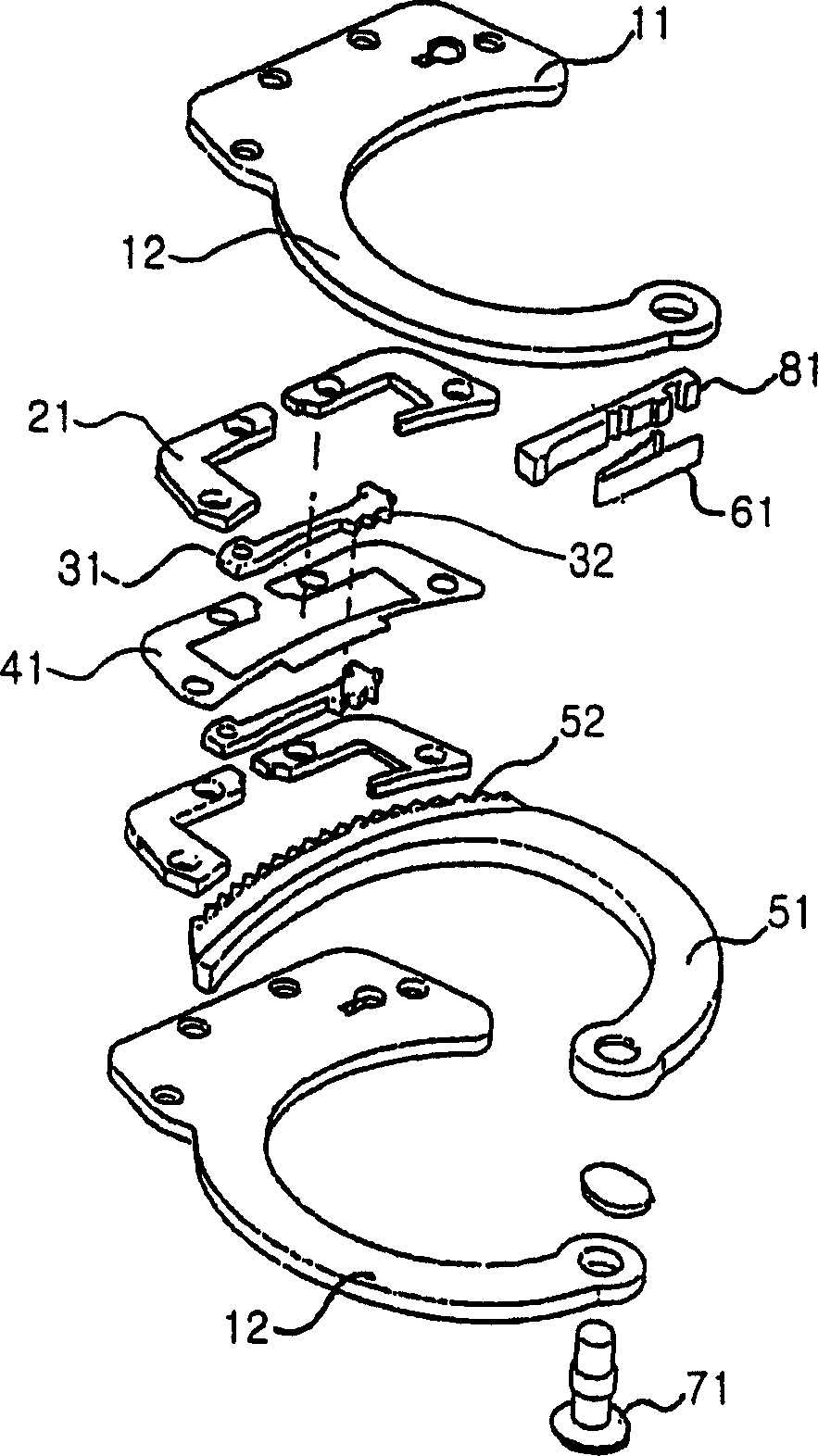
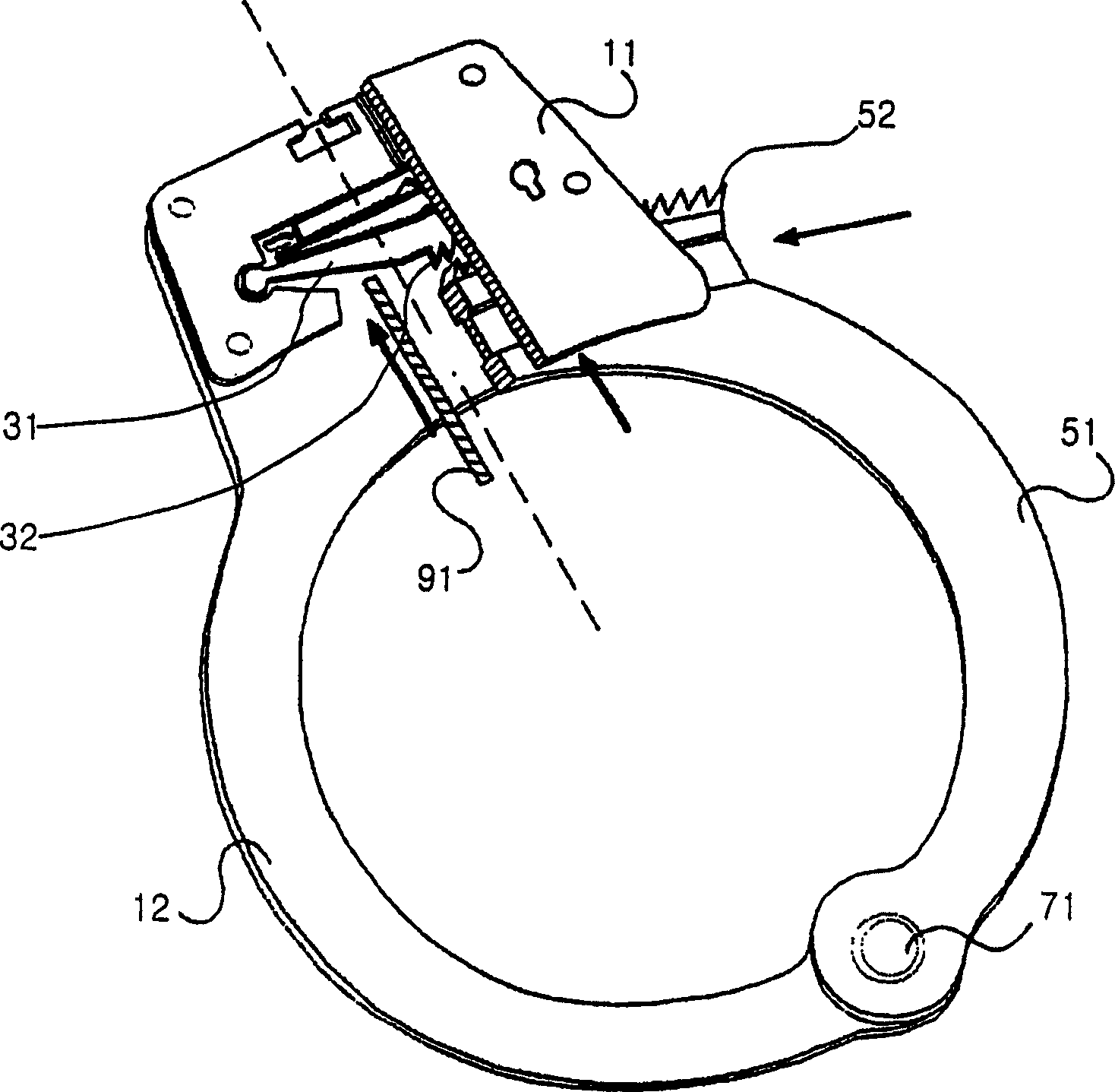
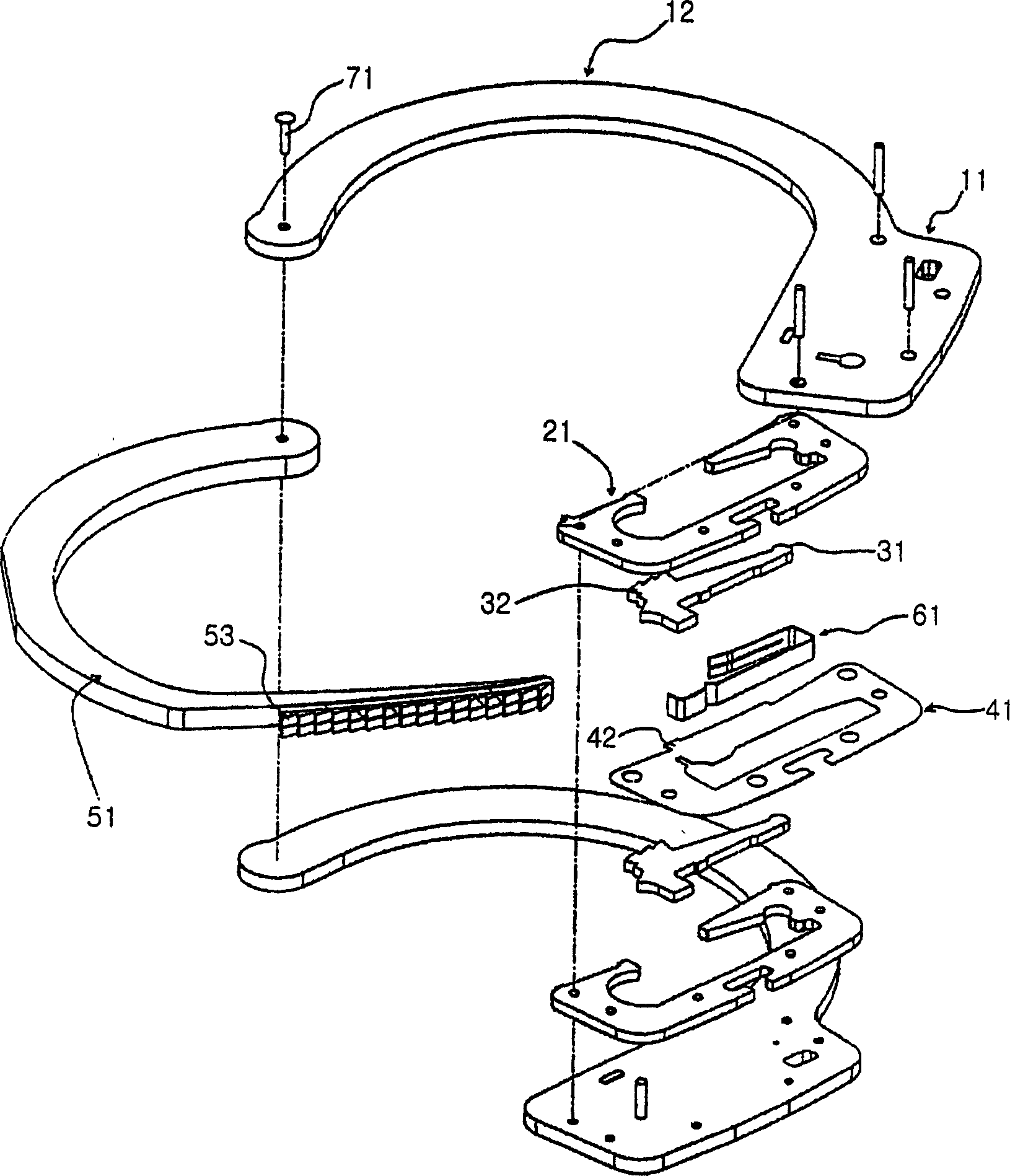
[0022] Such as Image 6 and Figure 7 As shown, the handcuffs according to the present invention include a pair of main bodies 11 , a spacer 21 , a spacer 41 , a leaf spring and a movable arm 51 . The pair of main bodies 11 respectively have fixed arms 12 integrally formed therewith. The positioning frame 21 is used to movably receive the anti-reverse member 31 inside the main body 11 . Each backstop 31 is formed with a ratchet protrusion 32 on one end. The backstop 31 is movably held inside the positioning frame 21 . The spacer 41 is used to isolate the anti-reverse part 31 . The leaf spring serves to elastically support the backstop 31 . The boom 51 has claws. The pair of main bodies 11 are combined together, and the spacer 21, the backstop 31, the spacer 41, the backstop 31, and the spacer 21 are placed between the tw...


PUM


Abstract

The handcuffs disclosed by the present invention include a swing arm with three rows of claws and a backstop member with three rows of ratchet protrusions corresponding to the three rows of claws, which can prevent suspects from illegally releasing the combination between the claws and the ratchet protrusions . The ratchet protrusions and boom pawls are triple combined so that even if a suspect illegally opens the handcuffs using a thin pin or other external thin piece along the boom receptacle on the side or underside of the body, it will only work if the ratchets are all released at the same time. The handcuffs can only be forcibly opened when there are three or more combinations between the tooth protrusions and the claws of the boom. Therefore, in fact, it is impossible to illegally open the handcuffs, therefore, the illegal opening of the handcuffs is fundamentally prevented.

Description

technical field [0001] The present invention relates to handcuffs, and more specifically, the handcuffs include a swing arm with three rows of claws and a non-return member with ratchet protrusions corresponding to the three rows of claws, thereby preventing the suspect from unlawfully unlocking the handcuffs. The joint between the open jaw and the ratchet protrusion. technical background [0002] Such as figure 1 As shown, in general, the handcuffs include a pair of main bodies 11 , a pair of non-reverse elements 31 , a pair of positioning frames 21 and a pair of spacers 41 . The pair of main bodies 11 respectively have fixed arms 12 integrally formed therewith. A ratchet protrusion 32 is formed at an end of the backstop 31 . The positioning frame 21 is used for receiving the anti-reverse member 31 in a movable manner. The spacer 41 is used to separate the positioning frame 21 from the backstop 31 . The positioning frame 21 , the non-return mem...

Claims


Application Information

Patent Timeline
Patent Type & Authority Applications(China)
IPC IPC(8): E05B75/00
CPCE05B75/00
Inventor 卢泰钟
Owner 卢泰钟
Learn More