Biomass pyrolysis liquefied technique and double tower apparatus system thereof

A biomass pyrolysis and process method technology, which is applied in the field of biomass regeneration and utilization and its energy utilization, achieves the effects of increasing the heating rate, being beneficial to control, and realizing energy saving and consumption reduction.

Inactive Publication Date: 2006-02-08
CHONGQING UNIV
View PDF1 Cites 69 Cited by
  • Summary
  • Abstract
  • Description
  • Claims
  • Application Information

AI Technical Summary

Problems solved by technology

Therefore, this application can only be used for mechanistic studies of biomass pyrolysis

Method used


Image

  • Biomass pyrolysis liquefied technique and double tower apparatus system thereof

Examples


Embodiment 1

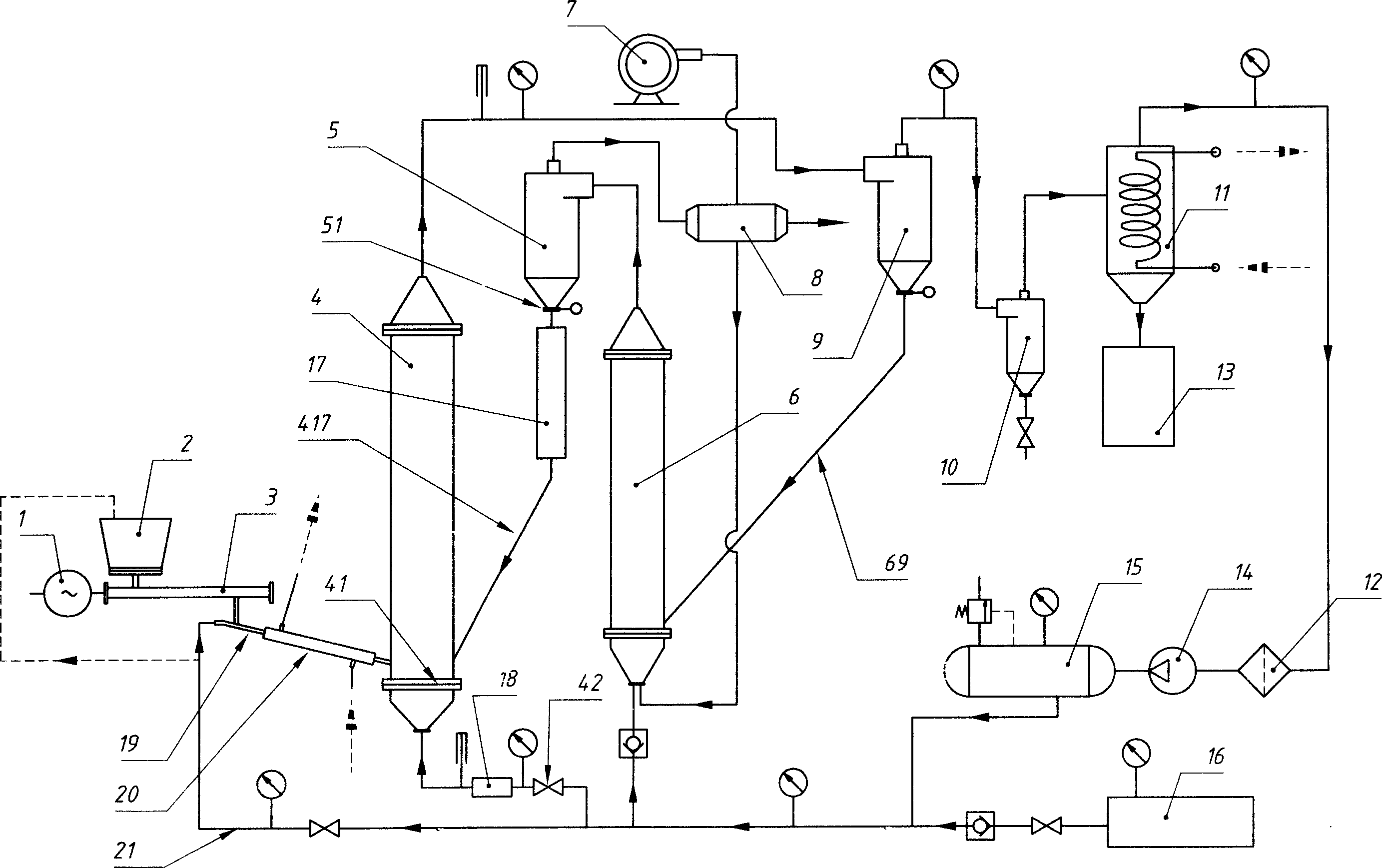
[0037] This example is based on the general description, and aims at the further specificity of the manner or structure in which the heating medium residual carbon circulation pipe 69 and the heating medium return pipe 417 transport the substances in the pipes. That is: in the device system of this example, the heating medium residual carbon circulation pipe 69 is inclined, and the inlet end of the circulation pipe 69 at the primary separator 9 is higher than the opening of the circulation pipe 69 at the heating medium heating tower 6 place. Outlet end; Similarly, heat carrier return pipe 417 is also inclined, and the inlet end of this return pipe 417 at heat carrier thermostat 17 place is higher than the outlet end of this return pipe 417 at pyrolysis reaction tower 4 places; The included angles between the inclination directions of the pipes (69, 417) and the horizontal plane are greater than 45°. That is to say, in this example, rely on the gravity of heat carrier and resid...

Embodiment 2

[0039] This example is on the basis of the general description part or embodiment 1, aiming at the further optimization of the heating rate of the pyrolysis reaction tower 4, that is: on the pipeline where the fluidization gas is imported into the pyrolysis reaction tower 4, another fluidization Gas thermostat 18. In other words, just in case the preheated heat carrier is not enough to increase the temperature rise rate in the pyrolysis reaction tower 4, the fluidizing gas thermostat 18 can be used to control the flow of the input into the pyrolysis reaction tower 4. Tempering of vaporized gas - preheating if necessary. At the same time, a corresponding thermometer should also be installed here. Of course, if conditions permit, the closer the fluidization gas thermostat 18 is to the input port at the bottom of the pyrolysis reaction tower 4, the better.

Embodiment 3

[0041] This example is based on the general description, Example 1 or Example 2, and is aimed at the further specificization of the mode or structure of auxiliary conveying of biomass powder with circulating carrier gas. That is: in the device system of this example, the feeding mechanism includes a screw conveying device 3 and a feed pipe 19 connected between the outlet of the screw conveying device 3 and the inlet of the pyrolysis reaction tower 4. The carrier gas input pipe is connected in the feed pipe 19 in the structural form of the injector, and the biomass powder is carried out auxiliary transportation in the mode of entrainment to allow the circulating carrier gas (because the structural form of the injector belongs to the technology of the field Personnel are clear, so a partially enlarged cross-sectional view is not drawn separately). Obviously, this example is an applicable structure under the condition that the dynamic pressure of the carrier gas in the carrier ga...


PUM


Abstract

The invention relates to a biomass analgesic liquidation method and its twin-tower set system, the processes of which comprise the following steps: sending biomass to pyrolytic reaction tower and blending it with high-heat fluidized gas to subject biomass to pyrolytic cracking; separating thermal cracking gas with carbon residue and ash content in separator; and condensing thermal cracking gas to biological oil in condenser. In the process, heat-carrying agent is exported from pyrolytic reaction tower along with thermal cracking gas, carbon residue and so on, and carbon residue is used to preheat heat-carrying agent. The invention is special for heat-carrying agent heating tower to burn carbon residue and primary separator to separate heat-carrying agent, carbon residue and other materials. The invention can not only increase circulation rate to ensure uniform and stable temperature field in pyrolytic reaction tower, higher heating rates and shorter detention period of gas phase, but also make use of carbon residue as heat source by using existing apparatus.

Description

technical field [0001] The invention relates to the technical field of biomass regeneration and utilization and its energy conversion, in particular to a process method and a device system for pyrolysis and liquefaction of biomass. Background technique [0002] Energy is the basis for the survival and development of modern society. At present, more than 85% of my country's energy structure is coal, oil, natural gas and other non-renewable fossil fuels. These fossil fuels are not only increasingly scarce, but also cause serious pollution to the environment in the large cycle from mining to utilization. Therefore, seeking renewable clean energy has become a problem of great concern to all countries in the world. Biomass (including various agricultural wastes, fast-growing firewood forests, wastes from forestry and wood processing industries, aquatic plants and various organic wastes, etc.) is the raw material of renewable and clean energy produced through photosynthesis. Bi...

Claims


Application Information

Patent Timeline
Patent Type & Authority Applications(China)
IPC IPC(8): B09B3/00
Inventor 龙恩深王亮马校飞崔天赵建辉蒋琳
Owner CHONGQING UNIV
Why Eureka
Try Eureka