
Disposable filter floor stand

A disposable, filter cartridge technology, applied in the field of floor supports, can solve problems such as occupancy, inability to work, and large footprint, and achieve the effects of easy use, compact storage, and easy cleaning

Inactive Publication Date: 2006-03-08
MILLIPORE CORP
View PDF0 Cites 0 Cited by
  • Summary
  • Abstract
  • Description
  • Claims
  • Application Information

AI Technical Summary

Problems solved by technology

Because some containers are designed to operate in a "bell up" position, where the inlet and outlet are at the bottom and the rest of the container protrudes upwards, they will not work or will not work in the bell up position work effectively
[0007] This design is stationary and takes up a large footprint both in use and in storage
Finally, the device has many crevices and hooks that are difficult to clean

Method used


Image

  • Disposable filter floor stand
  • Disposable filter floor stand
  • Disposable filter floor stand

Examples


Embodiment Construction

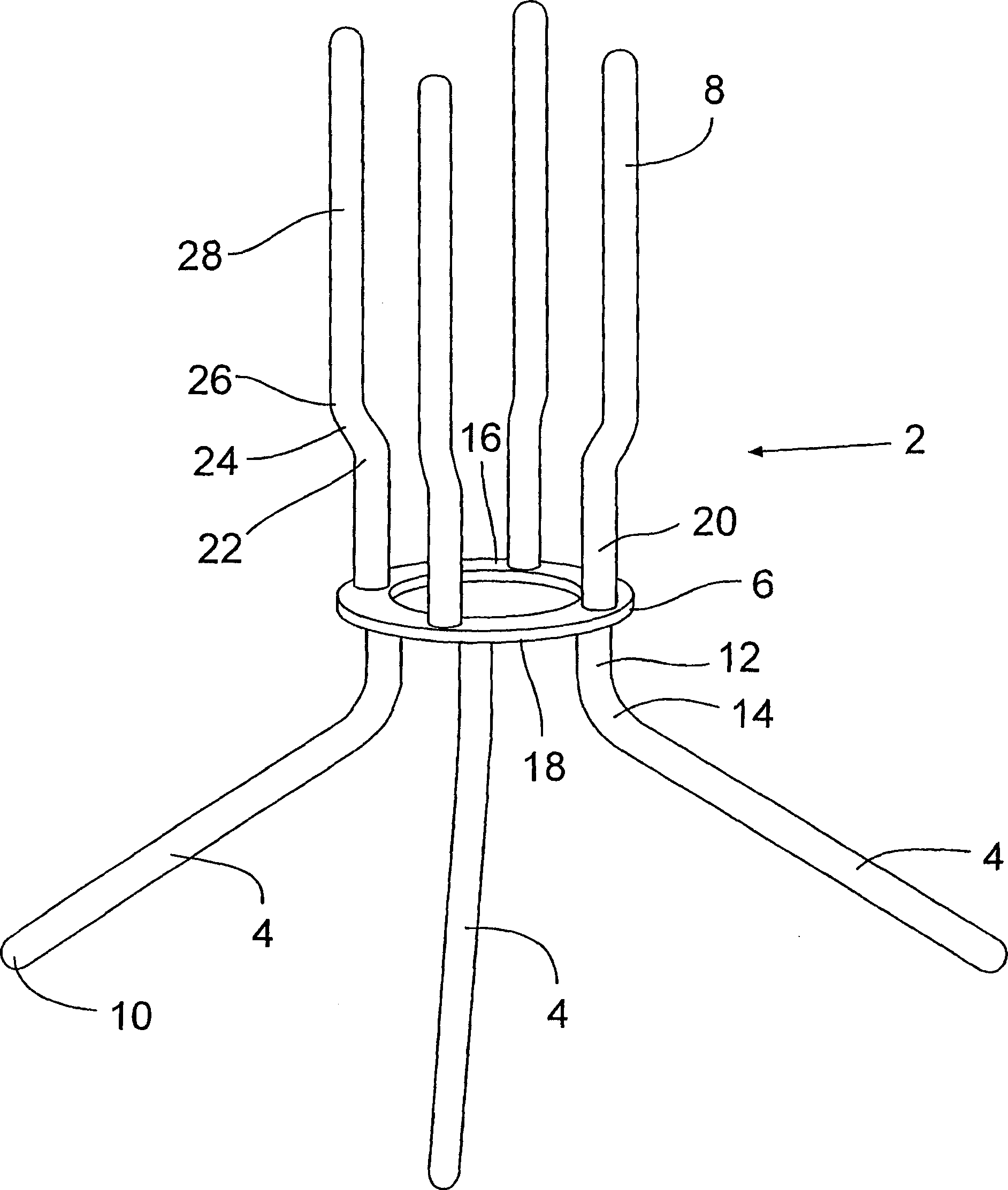
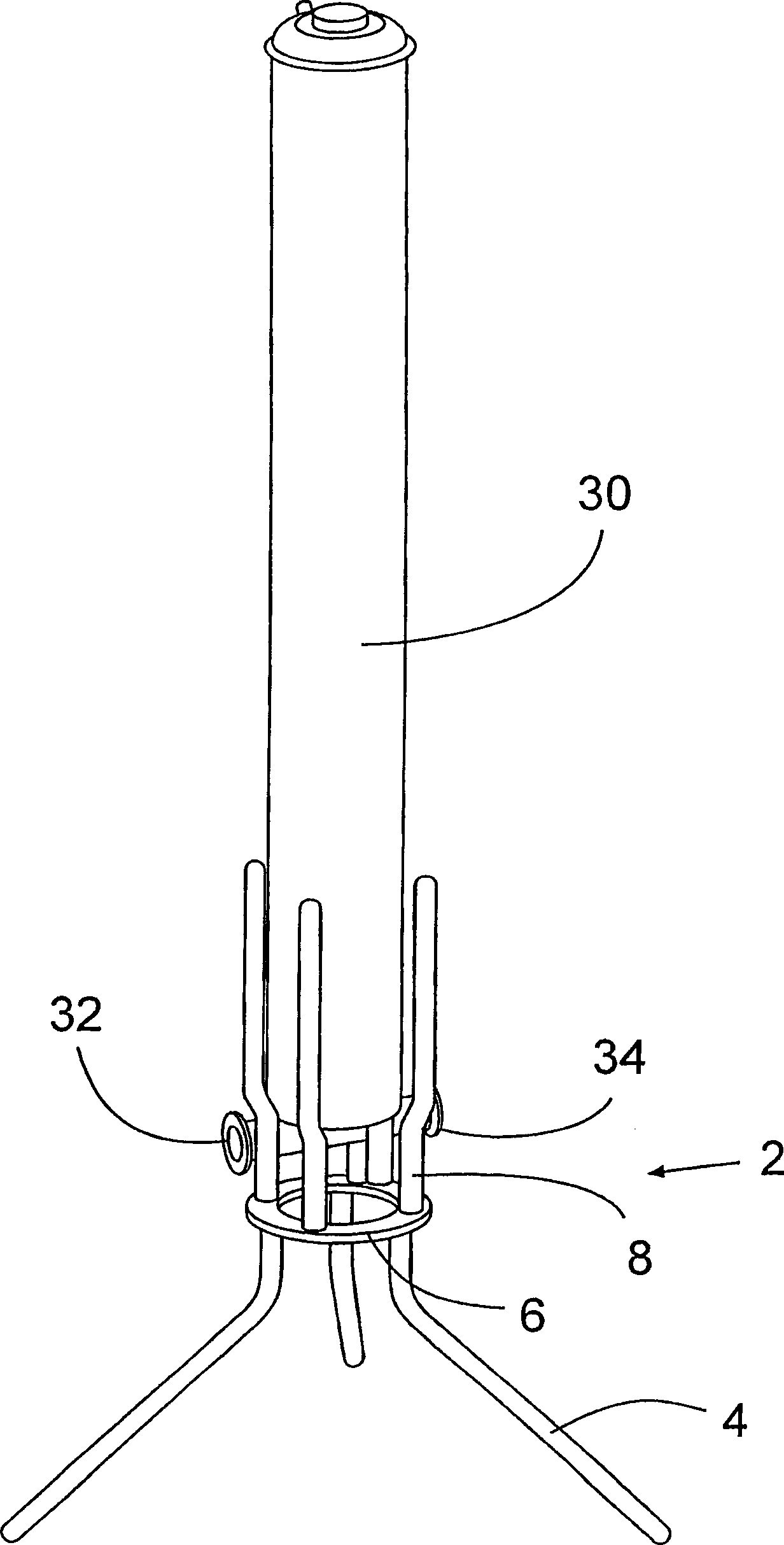
[0023] figure 1 A floor stand 2 according to an embodiment of the invention is shown.

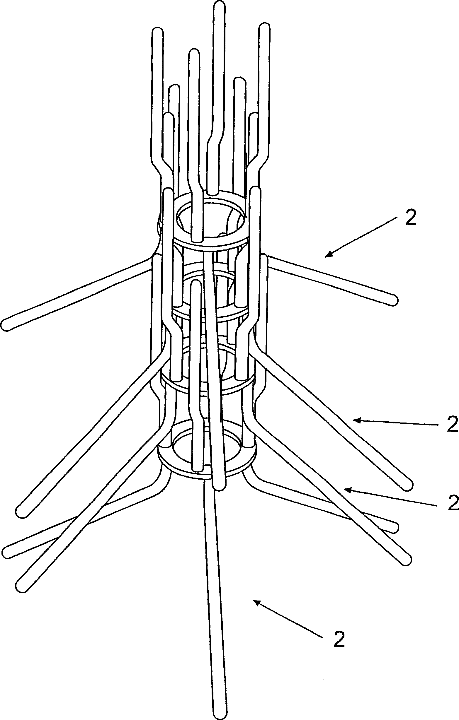
[0024] The stand 2 has 3 main parts: three or more legs 4 , a base 6 and three or more support arms 8 . As shown, there may be three legs 4 and four arms 8 .

[0025] As shown, each leg 4 in this embodiment consists of two sections; a portion 10 that contacts the ground, and a portion 12 that mates with the base 6 . The two parts 10, 12 are mated to each other by a beveled portion 14 forming an angle between them. Typically, the base portion 12 of the leg 4 is substantially vertical and the landing portion 10 protrudes outwardly and downwardly, preferably at an angle between about 0° and about 90° from the vertical. The angle may be defined by the centerline of the sloped portion 14 and the base portion 12 . Preferably, the angle is between about 15° and about 75°. In a preferred embodiment, this angle is approximately 54°.

[0026] In an alternative embodiment not shown, the leg itse...


PUM


Abstract

The present invention relates to a stand for holding disposable filter capsules and is formed of three or more legs, a base above the legs and to which the leg as are attached and three or more arms that are attached to an opposite surface of the base from that of the legs. The arms and legs have at least curved or angled portion that allows for the arms and legs to spread out from the diameter of the base. Preferably, the arms have a second curved or angled portion that then allows the upper portion of the arms to become substantially vertical.

Description

[0001] The invention relates to a ground support for a disposable filter. In particular, it relates to a floor stand for disposable filters that is light, easy to clean and occupies little floor space during use and storage. Background of the invention [0002] When a traditional "stand-alone" cartridge filter is used in biotechnology or pharmaceutical processing, it is usually inserted into a fixed stainless steel housing that can be fixed (or semi-fixed) mounted on a pharmaceutical processing line . [0003] In recent years the trend in the pharmaceutical / bio-industry field has shifted towards the use of disposable filter capsules as opposed to the stainless steel systems described above. The use of these disposable filter containers also presents challenges in clamping or securing the filter containers during production. [0004] These single-use container-based devices do not fit into conventional in-line or T-column stainless steel holders. They are often simply placed...

Claims


Application Information

Patent Timeline
Patent Type & Authority Applications(China)
IPC IPC(8): B01D46/12B01D46/42B01D53/86F16M11/00
CPCF16M11/00B01D46/2411F16M11/22B01D2265/06F16M11/16B01D53/86B01D46/0005
Inventor 苛蒂斯·瑙斯达斯蒂芬·P·普罗克斯凯文·G·麦金纳尼约瑟夫·M·阿尔马希恩阮洲杰里米·C·佩罗
Owner MILLIPORE CORP
Learn More