Double clutch transmission

一种双离合器、变速器的技术,应用在混合动力车辆、齿轮传动装置、车辆子单元功能等方向,能够解决位置问题等问题

Inactive Publication Date: 2006-11-01
GETRAG FORD TRANSMISSIONS GMBH
View PDF2 Cites 13 Cited by
  • Summary
  • Abstract
  • Description
  • Claims
  • Application Information

AI Technical Summary

Problems solved by technology

However a motor of this size can also cause positional problems

Method used


Image

  • Double clutch transmission
  • Double clutch transmission
  • Double clutch transmission

Examples


Embodiment Construction

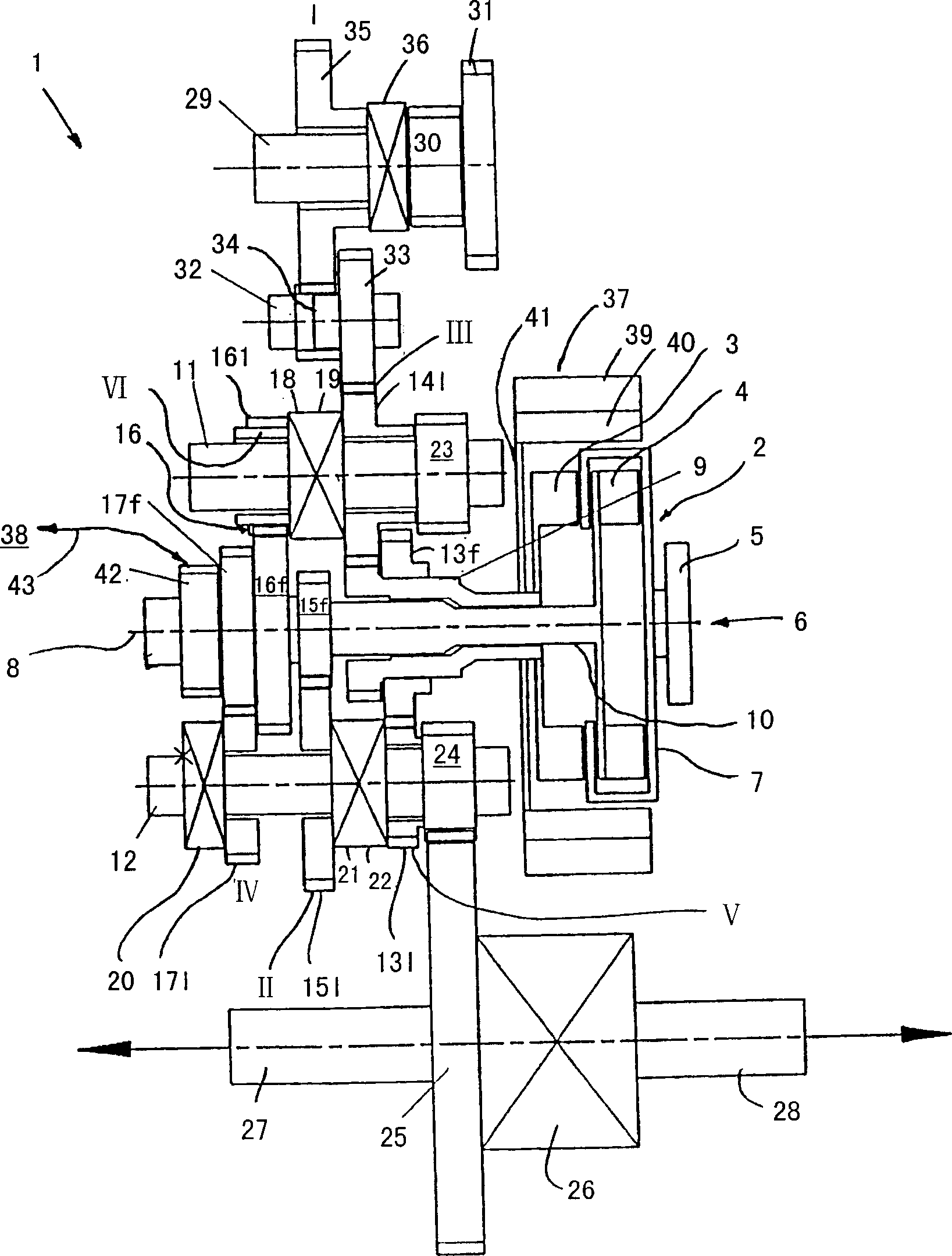
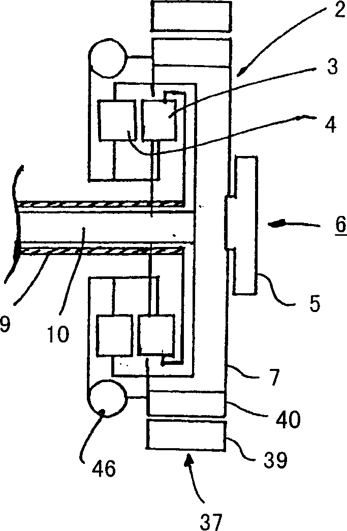
[0024] figure 1 A dual clutch transmission is shown, which is generally designated 1 . The dual clutch transmission 1 has a dual clutch arrangement 2 with a first clutch 3 and a second clutch 4 . On an input side 7 of the dual clutch device 2 , a motor 6 , which is only schematically represented here, can be fixed to a flange 5 in a rotationally fixed manner.

[0025] The first clutch 3 and the second clutch 4 have a common axis of rotation 8 . A first input shaft 9 and a second input shaft 10 are arranged coaxially with the axis of rotation 8 . The input shaft 9 is designed as a hollow shaft. In this case, the first clutch 3 in the closed state connects the first input shaft 9 to the input side 7 of the dual clutch device 2 or to the engine 6 . The second clutch 4 serves to connect the second input shaft 10 to the engine 6 .

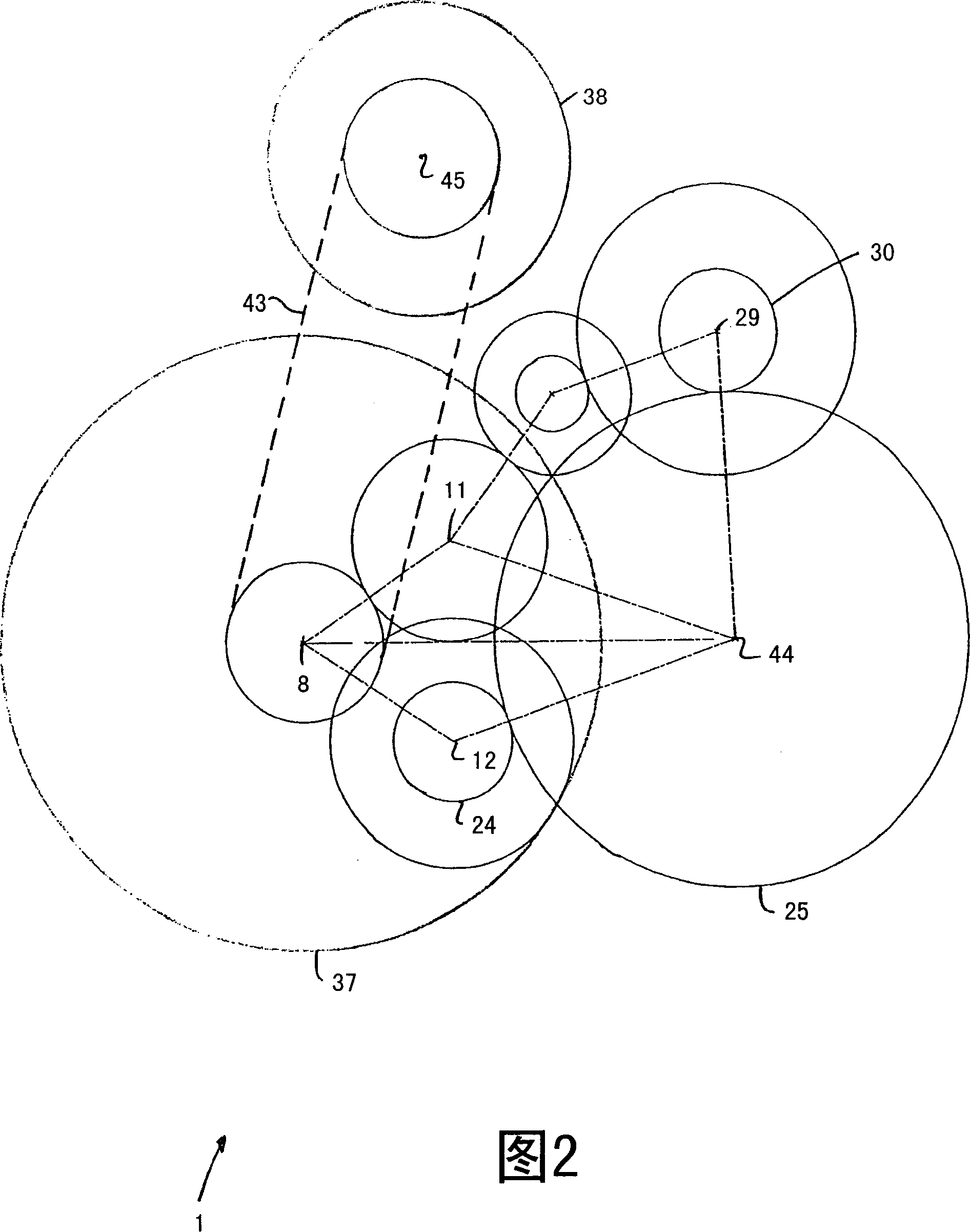
[0026] The dual clutch transmission 1 also has a first output shaft 11 and a second output shaft 12 . The respective axes of rotation of the two ...


PUM


Abstract

A twin-clutch transmission, in particular for a motor vehicle, with a twin-clutch arrangement comprising: a first clutch; a second clutch; a first input shaft; a second input shaft; at least one output shaft; a number of engageable gearwheel pairs for connecting the input shafts to the at least one output shaft; a first drive unit; and a second drive unit having a drive shaft rotatable around a rotational axis. The clutches having a common rotational axis connect the first and second input shafts to an engine. A serial and / or parallel hybrid mode of the twin-clutch transmission can be established by means of the first and second drive units. The first drive unit is arranged coaxially with the first and second clutches and surrounds the clutches in the radial direction. The drive shaft of the second drive unit and the clutches have different rotational axes.

Description

technical field [0001] The invention relates to a dual clutch transmission, in particular for use in motor vehicles. Background technique [0002] For example, US Pat. No. 6,499,370 discloses a dual-clutch transmission comprising a first clutch and a second clutch, which are arranged coaxially with one another and thus have a common axis of rotation. Furthermore, the dual clutch transmission includes a first input shaft and a second input shaft. In this case, the first input shaft can be connected to a motor via a first clutch. The second input shaft can be connected to the engine by a second clutch. [0003] Torque can be transmitted from an input shaft to an output shaft via several shiftable gear pairs. A gear pair consists of a fixed gear and a loose gear. Each of the loose gears is correspondingly equipped with a shift clutch, through which the loose gear can be connected to the shaft where the loose gear is located without relative rotation. The gear pair transmit...

Claims


Application Information

Patent Timeline
Patent Type & Authority Applications(China)
IPC IPC(8): F16H3/08B60K6/40B60K6/547
CPCB60K6/36B60K6/40B60K6/46B60K6/48B60K6/547B60Y2400/428F16H3/006Y10T74/19284Y10T74/19223Y10T74/19233Y10T74/19288Y10T74/19219Y10T74/19228Y02T10/62
Inventor 乌尔里希·埃格特克里斯蒂安·克劳斯马丁·莱布兰特
Owner GETRAG FORD TRANSMISSIONS GMBH
Why Eureka
Try Eureka