
Spray nozzle

A technology of nozzles and injection ports, which is applied in the field of nozzles and can solve problems such as turbulent entry

Active Publication Date: 2007-01-10
NIPPON VINYLON
View PDF5 Cites 1 Cited by
  • Summary
  • Abstract
  • Description
  • Claims
  • Application Information

AI Technical Summary

Problems solved by technology

[0003] However, existing nozzles such as Figure 8B Or as shown in 8C, if the spray liquid flows along the inner peripheral wall surface to the concentration point, it will collide with each other and enter in disorder, and spray from the spray port 15 along one side of the diffusion guide plate 13, 14 irregularly.
For this reason, the water impact position at the time of spraying changes, and there is a problem of stably spraying at the water impact position.

Method used


Image

  • Spray nozzle
  • Spray nozzle
  • Spray nozzle

Examples


Embodiment Construction

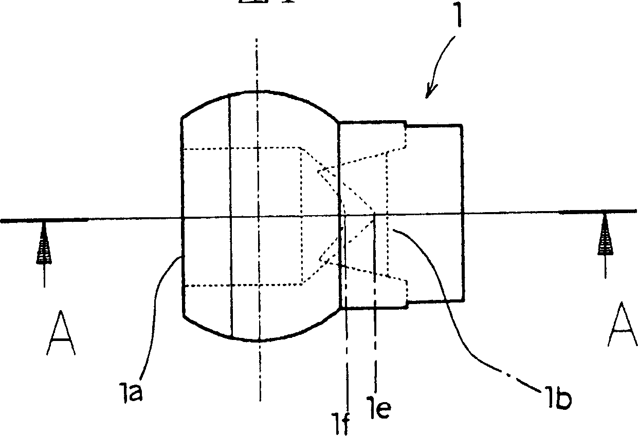
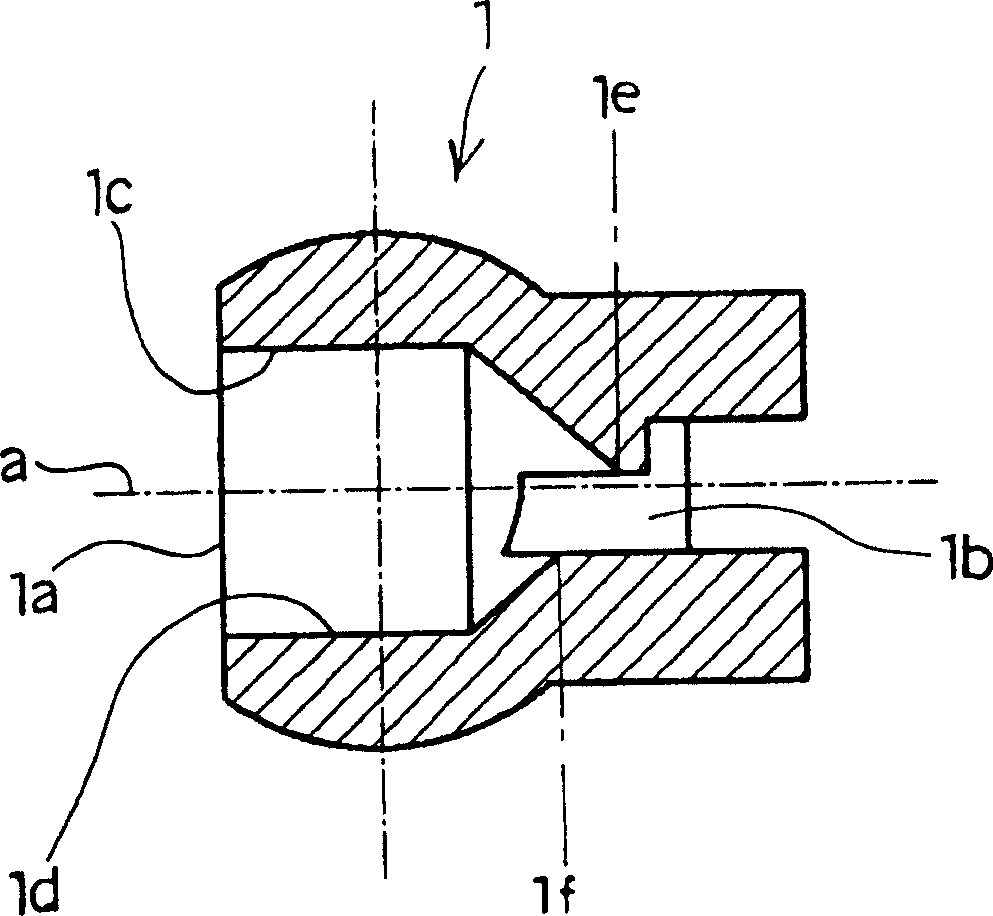
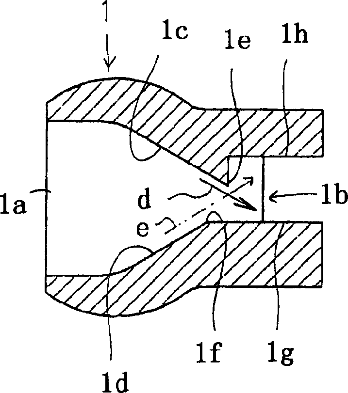
[0019] The nozzle 1 according to the present invention is, for example, a washer nozzle for spraying a washer fluid onto a windshield of an automobile. Such as figure 1 and figure 2 As shown, in the flow path reaching the supply port 1a and the horizontally formed ejection port 1b in the nozzle 1, the cross-sectional area of ​​the flow path is gradually reduced to form a structure consisting of upper and lower inner peripheral wall surfaces 1c and 1d reaching the ejection port. of the cone. The upper position 1e and the lower position 1f of the injection port-side ends of the tapered portions 1c and 1d are formed to be offset from each other in the direction of the axis a of the flow path. In the illustrated embodiment, the position 1e of the upper jet port side end is as follows figure 2 As shown, it is disposed closer to the injection port 1b side with respect to the position 1f of the lower side end portion on the injection port side.

[0020] As for the positions 1e...


PUM


Abstract

The invention provides a spray nozzle (1) in which the position at which the spray fluid strikes a target does not change. The spray nozzle includes an injection port (1b) formed long from side to side, a flow path formed cylindrical between a supply port (1 a) and the injection port, the flow path having a taper section (1c, 1d) formed on the middle thereof, reducing the flow path cross-sectional area gradually and a tip end being reached to the injection port, wherein upper and lower positions (1e and 1f) of the taper section at an end portion on the injection port side are offset with respect to each other in the direction of the axis of the flow path.

Description

technical field [0001] The present invention relates to a nozzle (spray-nozuru) used for a washer nozzle (wootsuya-nozuru) of an automobile or the like. Background technique [0002] In the prior art, nozzle 10 such as Figure 8A As shown, the spray liquid enters the flow path 12 from the supply port 11 behind the nozzle, and the flow path area is narrowed and concentrated in the middle. Glass etc. (refer to Unexamined-Japanese-Patent No. 2002-96718). [0003] However, existing nozzles such as Figure 8B Or as shown in 8C, when the spray liquid flows along the inner peripheral wall surface to a concentration point, it collides with each other and enters in disorder, and sprays irregularly from the spray port 15 along one side of the diffusion guide plates 13 and 14 . For this reason, the water impact position at the time of spraying changes, and there is a problem of stably spraying at the water impact position. The nozzle according to the present invention is proposed in...

Claims


Application Information

Patent Timeline
IPC IPC(8): B05B1/02B08B3/02B08B3/04
CPCB05B1/04
Inventor 山口高广
Owner NIPPON VINYLON
Features
  • Generate Ideas
  • Intellectual Property
  • Life Sciences
  • Materials
  • Tech Scout
  • Unparalleled Data Quality
  • Higher Quality Content
  • 60% Fewer Hallucinations
Learn More