Mechanical logic device and mechanical safety device

A technology of mechanical logic and anti-theft device, applied in the field of mechanical logic

Active Publication Date: 2007-01-17
高瞩宇
View PDF1 Cites 15 Cited by
  • Summary
  • Abstract
  • Description
  • Claims
  • Application Information

AI Technical Summary

Problems solved by technology

[0004] Another technical problem to be solved is: to provide a mechanical anti-theft device for the structural problems existing in the current anti-theft field. The process makes logical judgments and performs different logic control processing to achieve the purpose of anti-theft. For example, the key to anti-theft doors is locks. In order to prevent technical unlocking, a multi-digital lock is designed. Self-locking, to prevent technical unlocking; for locks with keys, an anti-test opening lock body can be used, which is the different actions when the original key and the master key are unlock...

Method used


Image

  • Mechanical logic device and mechanical safety device
  • Mechanical logic device and mechanical safety device
  • Mechanical logic device and mechanical safety device

Examples


Embodiment 1

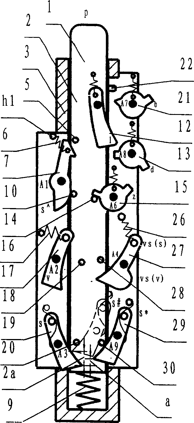
[0067] figure 1 It is a mixed double-position device with a click structure. There is a column head 1 at the upper end of the cylinder 2 in the groove of the housing 3. The lower spring 9 can make the column head protrude out of the shell. There is a self-returning locking mechanism for the click piece 7 to rotate around the axis A1. There is a hook on the upper part to lock the column pin 5, and the positioning spring 6 can keep the catch 7 at the unlocked or locked position. K31 of 7 is under the action of the column pin 10, the catch rotates clockwise, and the spring returns to the lockable position when it surpasses the connection line between h1 and A1. 17 When turning counterclockwise, its lower end can lock the pin 18, and the spring 16 always makes the lower end of the pawl leave the pin 18 in the unlocked position. Only when there is a rightward thrust at point v, it is in the locked position, and the normal locking mechanism is the axis. The pin 20 can be locked on ...

Embodiment 2

[0072] As shown in Figure 4, it is a wheel-type mixed double-position device with a click structure, which is composed of a housing, a wheel mechanism, a locking mechanism, a reset mechanism and a force output mechanism. The wheel mechanism is provided in the housing 53 so that the wheel 52 can rotate around its central axis 55. A pin is arranged on the wheel, and a spring 59 is installed on the wheel and the housing so that the wheel rotates counterclockwise to the limit position, and the wheel is pushed clockwise. The pin 54 can make the wheel return to the original position, that is, the reset position, and the pin is used as the reset force input terminal r; the locking mechanism is that a locking catch 19 is arranged between the wheel and the housing, and its left end can lock the wheel pin 20, and the wheel is locked in the reset position. position, when the lock is released, the wheel turns to the limit position under the action of the spring spring, which can make it a ...

Embodiment 3

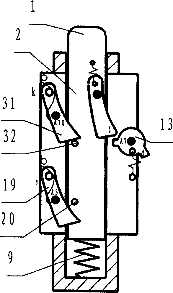
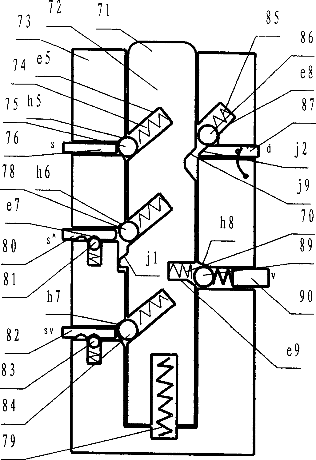
[0076] Figure 7 Shown is a column counter structure, which is composed of the above-mentioned pin-shaped column-type mixed double-position device configured with a counting input mechanism. The locking mechanism of the mixed double-position device is set in multiple positions, and there are springs and pins 75 in the cylinder groove e5. , and correspondingly provided with inclined holes h2, h3, h4, h5 in the housing groove, which can form locking mechanisms in different positions with the pin 75 in the slot e5, such as when the pin 75 is in h5, the locking cylinder is in the reset position or set to 0 position, the marbles are set to 1, 2, and 3 in the holes h4, h3, and h2 respectively. As shown in the figure, the pins are set to 1 in the hole h4. If the working height of the cylinder spring 79 is sufficient, you can set more Multiple digits. The counting input mechanism is composed of a pin pulse force generating mechanism and an unlocking lever. When the pressing bar 39 is...


PUM


Abstract

A mechanical logic component such as mixed two-position component, wheel type of two-position component, displacement type of protector or controller, logic operator, mixed two-position counter, multiple digital lock, selectable type of antiprizing lock and unlock-test proof lock can be developed to be mechanical burglar proof devices such as sequencing burglar proof device, secondary protective burglar proof device of automobile, double-door burglar proof device, double-lock and double-alarm burglar proof door and secondary burglar proof new product with unlock-test and destructive unlock function.

Description

technical field [0001] The invention relates to mechanical logic technology, in particular to mechanical digital logic control application technology, a mechanical logic device and an anti-theft device using the mechanical logic device. Background technique [0002] At present, regarding the mechanical logic device in the present invention, the same inventor of the present invention applied for the Chinese patent "Mechanical Logic Application Method and Logic Device and Expression Connection Method and Application Device" on May 30, 2003 (application number: 03129048.5, publication date : December 8, 2004) and the mechanical logic device of the mechanical logic application method provided in the PCT application "Mechanical Logic Application Method and Mechanical Logic Device and Its Mechanical Logic Digital Lock" (PCT / CN2004 / 000529), which is available in some The application in the field is not convenient, such as equipment safety control, security and anti-theft fields wil...

Claims


Application Information

Patent Timeline
IPC IPC(8): G05G5/00G05G5/06G05G5/08G05G21/00E05B53/00E05B45/00B60R25/02B60R25/04
CPCE05B53/006E05B37/00
Inventor 高瞩宇
Owner 高瞩宇
Why Eureka
Try Eureka