
Sewing machine

A technology for sewing machines and actuating rods, which is applied in the field of sewing machines, can solve the problems of laborious reinsertion of the actuating rods, achieve the effect of eliminating the locking effect, reducing the requirements for locking the swing axis, and simple design

Active Publication Date: 2007-03-28
DURKOPP ADLER GMBH
View PDF4 Cites 2 Cited by
  • Summary
  • Abstract
  • Description
  • Claims
  • Application Information

AI Technical Summary

Problems solved by technology

The removal of the actuating lever and its reinsertion especially after the sewing machine has been turned back into the working position is laborious

Method used


Image

  • Sewing machine
  • Sewing machine
  • Sewing machine

Examples


Embodiment Construction

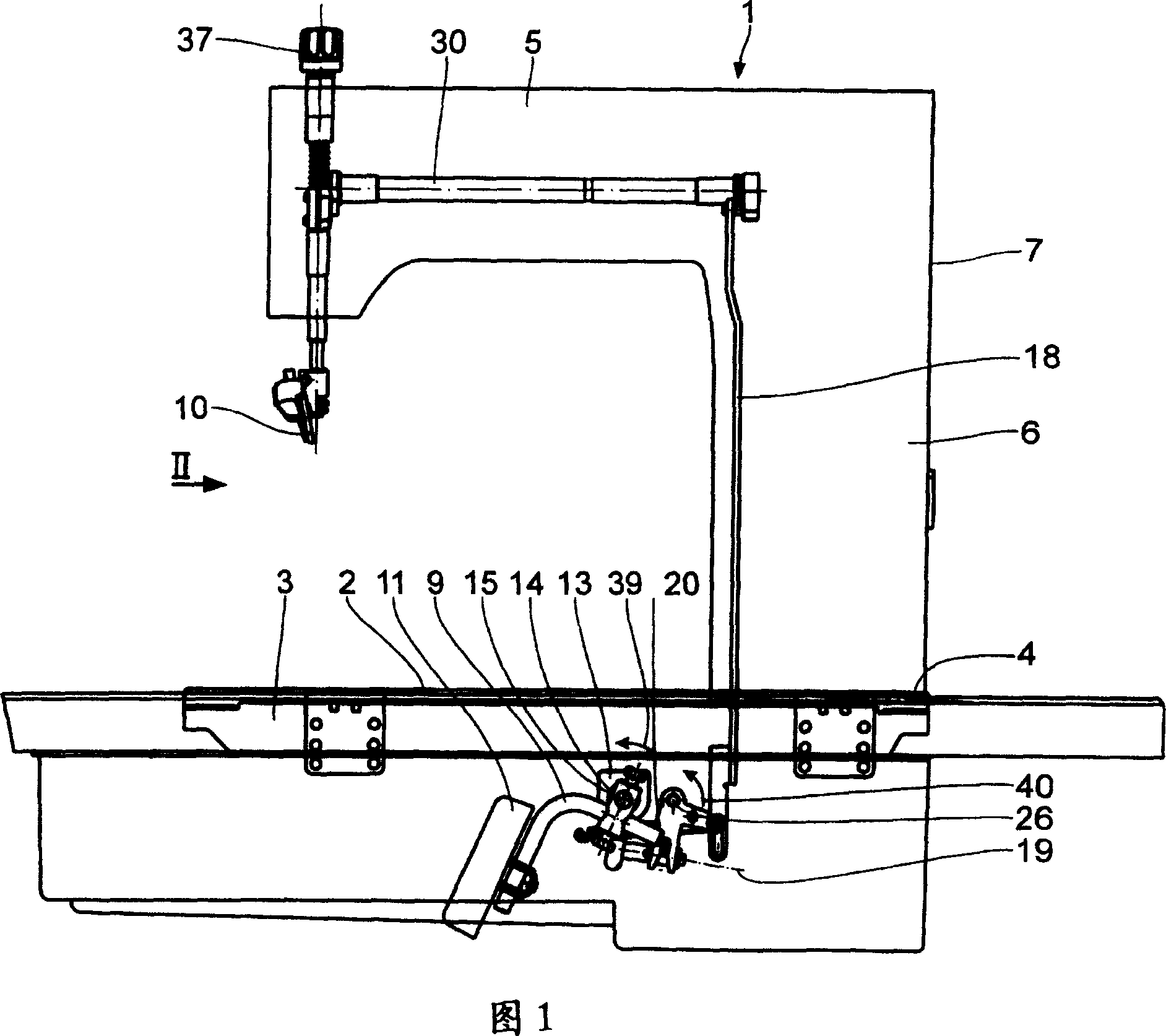
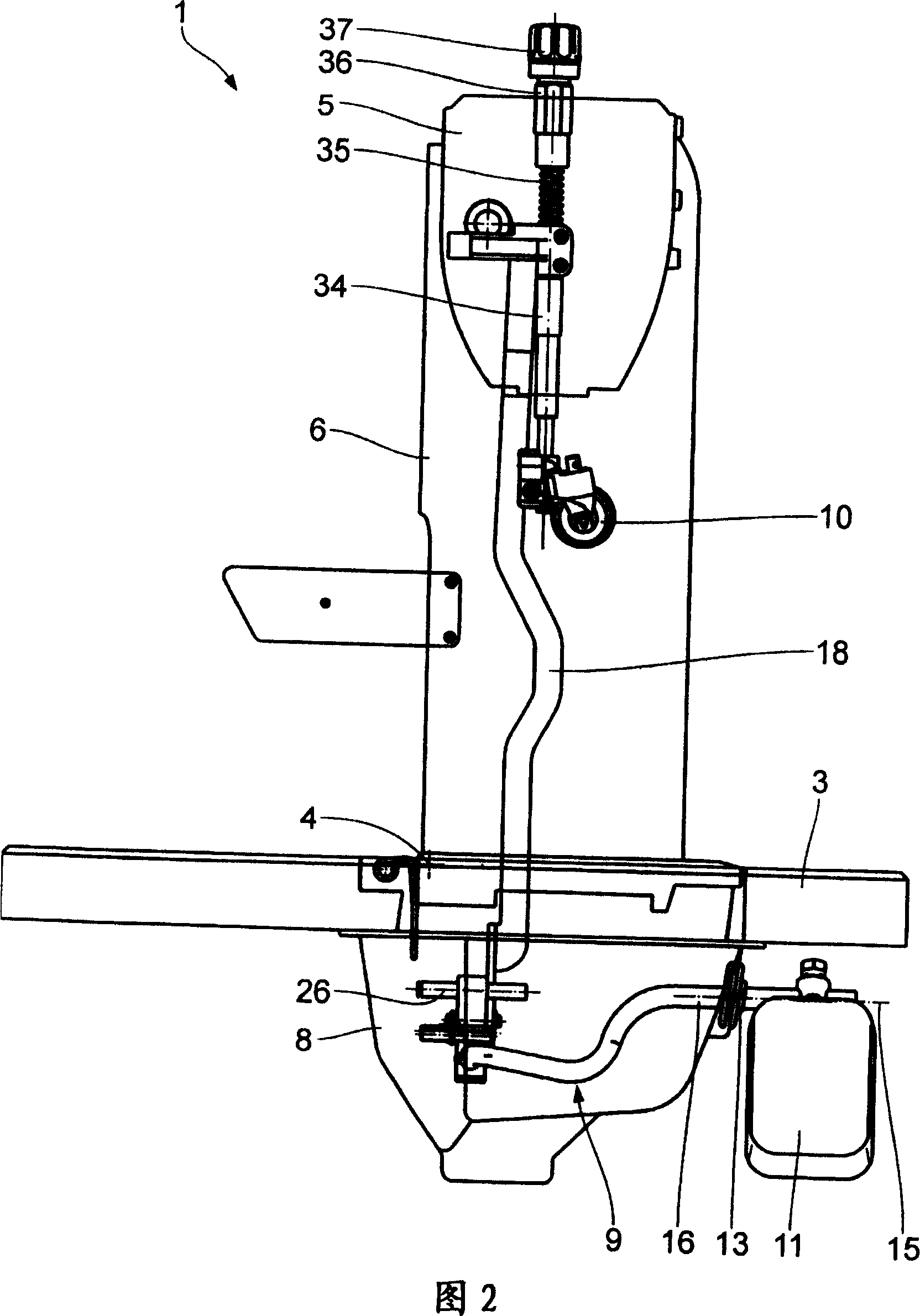
[0026] The sewing machine 1 has a base plate 2 on which—possibly also via intermediate components—the sewing material to be sewn can be placed. The base plate 2 rests on the carrier plate 3 . The base plate 2 can be pivoted about the pivot axis 4 relative to the support plate 3 via a pivot bearing (not shown in detail). The tilting axis 4 extends perpendicular to the projection plane of FIG. 2 and is located in the vicinity of the bearing area of ​​the base plate 2 on the bearing plate 3 on the side facing away from the user, in other words on the left side of the sewing machine 1 in FIG. 2 .

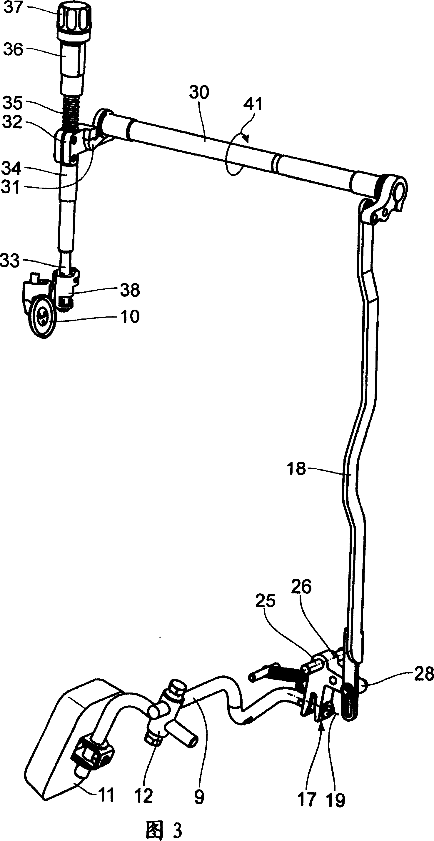
[0027] The sewing machine 1 has a top arm 5 and a column 6 connecting the base plate 2 and the top arm 5 . Below the support plate 3 , an actuating lever 9 emerges from a housing 7 of the sewing machine 1 , the housing being formed here by an oil sump 8 . The actuating lever 9 serves to raise a sewing tool, such as a roller foot 10 , of the sewing machine 1 . This raising to remove o...


PUM


Abstract

In a sewing machine (1) with a base plate (2), a support plate (3), a bearing for tilting the support plate relative to the base plate about a folding axis (4), an upper arm (5), a stand (6) connected to the base plate and upper arm and an operating lever (9) below the support plate, leading from a housing (7) and acting via a tilting element in combination with a lifting rod (18) in the stand for raising at least a sewing implement(s) (10), the operating lever is joined to the tilting element in such a way that the tilting of the lever relative to the rod about a tilting axis (19) approximately parallel to the folding axis is possible. Thus, the obtained sewing machine can easily turn over around the tilting axis without demolishing the operating lever.

Description

technical field [0001] The present invention relates to a sewing machine having [0002] - Substrate, [0003] - support plate, [0004] - a pivot support for pivoting the base plate about the pivot axis relative to the support plate, [0005] - top arm, [0006] - the uprights connecting the base plate and the top arm, [0007] - an actuation lever leading out from the housing of the sewing machine below the support plate for raising at least one sewing tool of the sewing machine, [0008] - The actuating lever for raising the suturing tool cooperates with a connecting rod extending in the column by pivoting of the deflection element about the axis of the lever. Background technique [0009] A sewing machine of this type is known from apparent previous use. A swing stand for swinging the base plate relative to the support plate is required for servicing the sewing machine. It is necessary to raise or lift at least one of the suture tools to remove or place the suture...

Claims


Application Information

Patent Timeline
IPC IPC(8): D05B29/02D05B73/00
CPCD05B29/02D05B75/02D05B27/10D05B27/12D05B29/00
Inventor P·维比哈尔M·马藻雷克
Owner DURKOPP ADLER GMBH
Learn More