
laser gyro

A technology of laser gyroscope and gyroscope, applied in the field of laser technology, can solve problems such as eliminating locking phenomenon, limiting the accuracy of laser gyroscope, and measurement accuracy error

Inactive Publication Date: 2015-09-16
NAT INST OF METROLOGY CHINA
View PDF4 Cites 0 Cited by
  • Summary
  • Abstract
  • Description
  • Claims
  • Application Information

AI Technical Summary

Problems solved by technology

These methods essentially add a disturbance in the ring cavity of the laser gyroscope, so that the laser frequency changes rapidly within a range, so that the lock-up threshold of the laser gyroscope changes continuously, and the lock-up of the laser gyroscope is avoided. Virtually eliminates lock-in
At the same time, the working mechanism of adding frequency disturbance is various, which brings errors in measurement accuracy.
And the introduction of bias frequency technology leads to certain restrictions on the measurement angle of the laser gyro. When the measurement angle is small to a certain extent, the error caused by the bias frequency will be greater than the result of the beat frequency of the measurement angle, resulting in unreliable measurement results of the laser gyro, which also directly limits The accuracy of the laser gyro

Method used

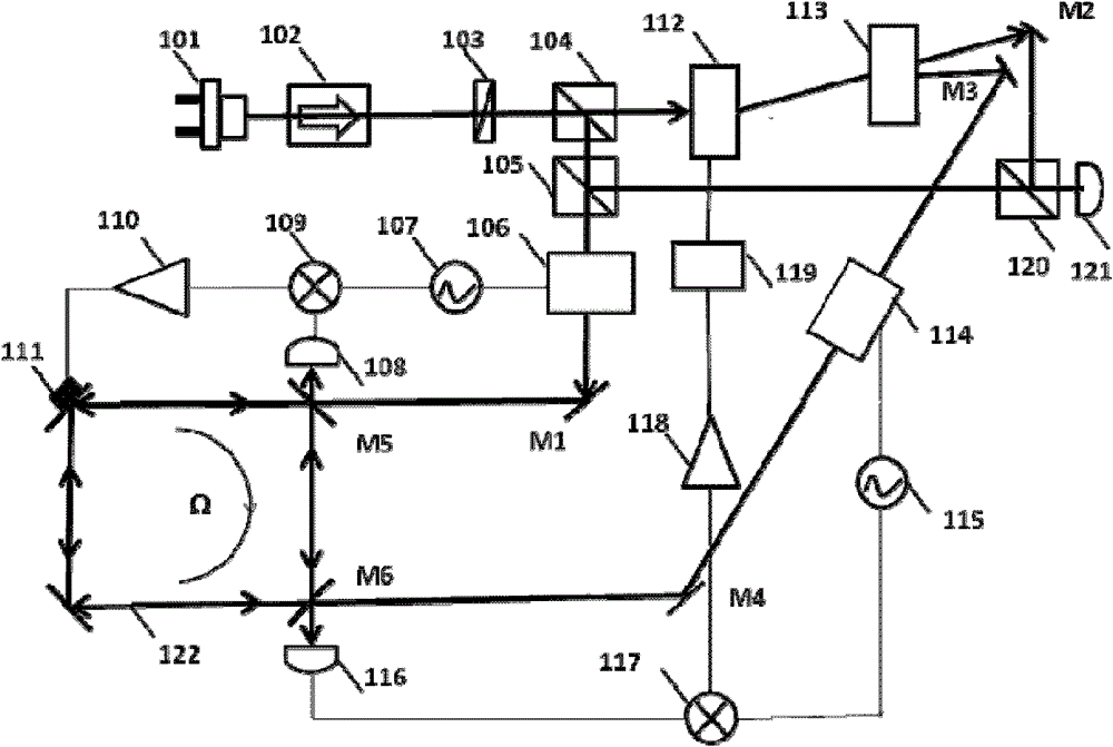
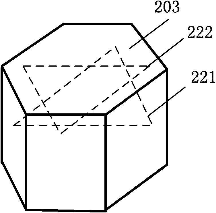

Image

  • laser gyro
  • laser gyro
  • laser gyro

Examples


Embodiment Construction

[0030] The present invention will be described more fully hereinafter with reference to the accompanying drawings, in which exemplary embodiments of the invention are illustrated.

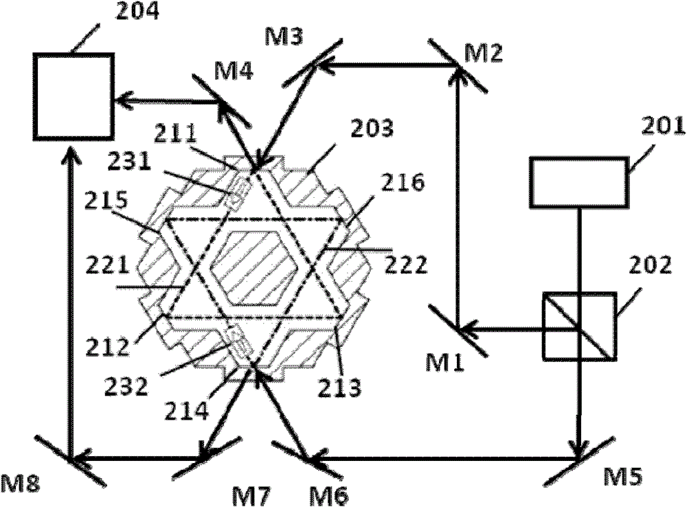
[0031] figure 2 It is a schematic diagram of an embodiment of the laser gyroscope of the present invention. Such as figure 2 As shown, the laser gyro includes a laser device 201, a polarization beam splitter prism 202, a gyro cavity 203, and a beat frequency measurement device 204, and the gyro cavity includes first to sixth side surfaces. in:

[0032] The laser device 201 is used for providing laser beams to the polarization beam splitter prism.

[0033] The polarizing beam splitter 202 is used to send the first beam formed by reflection to the first side surface 211 of the gyro cavity 203 after receiving the laser beam provided by the laser device 201, and send the second beam formed by transmission to The fourth side surface 214 of the gyro cavity 203 .

[0034] Wherein the first light be...


PUM


Abstract

The invention discloses a laser gyroscope. A polarization splitting prism sends a first light beam to the first side surface of a gyroscope cavity, a first optical path rotating in an anticlockwise manner is formed between the first side surface and the third side surface of the gyroscope cavity, and a first transmission light beam transmitted from the first side surface reaches the first input end of a beat frequency measuring device. The polarization splitting prism sends a second light beam to the fourth side surface of the gyroscope cavity, a second optical path rotating in a clockwise manner is formed between the fourth side surface and the six side surface of the gyroscope cavity, a second transmission light beam transmitted from the fourth side surface reaches the second input end of the beat frequency measuring device, and the beat frequency measuring device utilizes the first transmission light beam and the second transmission light beam to carry out beat frequency processing, wherein the first optical path does not overlap with the second optical path. The light beam optical path rotating in a clockwise manner and the optical path rotating in an anticlockwise manner do not overlap in the gyroscope cavity, so the interlocking effect is avoided, and the precision of the laser gyroscope is increased.

Description

technical field [0001] The present invention relates to laser technology, in particular to laser gyroscopes. Background technique [0002] Since the 1960s, the laser gyroscope has played a huge role in national defense and civilian fields. It is the only non-electromechanical high-precision inertial sensitive instrument that has really been applied in the field of inertial technology so far. Compared with conventional electromechanical gyroscopes, laser gyroscopes have the characteristics of high reliability, long life, high precision and low cost. At present, the air forces of all countries in the world use laser gyroscopes as standard equipment for air force systems for positioning and navigation, and various large and medium-sized civil aviation airliners are also equipped with laser gyroscope inertial reference systems. At the same time, laser equipment has begun to be used on ships and land equipment. develop. [0003] At present, laser gyroscopes are based on the Sag...

Claims


Application Information

Patent Timeline
IPC IPC(8): G01C19/64
Inventor 臧二军曹红军杨涛李烨林弋戈王少凯曹建平方占军
Owner NAT INST OF METROLOGY CHINA
Learn More