Supercharge Your Innovation With Domain-Expert AI Agents!

Clock generation circuit and method of generating clock signals

A clock generation circuit and clock signal technology, applied in the direction of generating/distributing signals, generating electrical pulse circuit components, generating electrical pulses, etc., can solve problems such as long ring locking time, output clock signal error, phase error, etc.

Inactive Publication Date: 2007-05-02
SAMSUNG ELECTRONICS CO LTD
View PDF0 Cites 12 Cited by
  • Summary
  • Abstract
  • Description
  • Claims
  • Application Information

AI Technical Summary

Problems solved by technology

If the control voltage Vc includes noise, the output clock signals (CLK0-CLK270 and FCLK) contain errors, such as phase errors
Also, as mentioned above, traditional DLLs have the disadvantage of relatively long ring lock times

Method used


Image

  • Clock generation circuit and method of generating clock signals
  • Clock generation circuit and method of generating clock signals
  • Clock generation circuit and method of generating clock signals

Examples


Embodiment Construction

[0070] Various example embodiments of the present invention will now be described more fully with reference to the accompanying drawings in which some example embodiments of the invention are shown.

[0071] Detailed illustrative embodiments of the invention are disclosed herein. However, specific structures and functions disclosed herein are merely representative for describing example embodiments of the present invention. However, this invention may be embodied in many different forms and these should not be construed as limited to only the embodiments set forth herein.

[0072] Therefore, while the example embodiments of the present invention are capable of various modifications and alternative forms, embodiments thereof are shown by way of example in the drawings and will be described herein in detail. It should be understood, however, that the intention is not to limit embodiments of the invention to the particular forms disclosed, but on the contrary example embodiments...


PUM


Abstract

Clock generation circuit and method of generating clock signals. The clock generation circuit includes an inverter directly receiving an external clock signal and outputting an inverted external clock signal, M (where M is an integer >=1) loop circuits arranged in series, the first loop circuit receiving the inverted external clock signal, each of the N loop circuits having n (where n is an integer >=2) nodes, each of the M-1 loop circuits generating n intermediate internal clock signals, each at a corresponding one of the n nodes, wherein a frequency of the n intermediate internal clock signals is a multiple of a frequency of the external clock signal and the inverted external clock signal; and n sets of inverters, each including M-1 inverters connected in series, each of the M-1 inverters receiving a corresponding intermediate internal clock signal from a previous loop circuit and outputting a corresponding intermediate internal clock signal to a next loop circuit.

Description

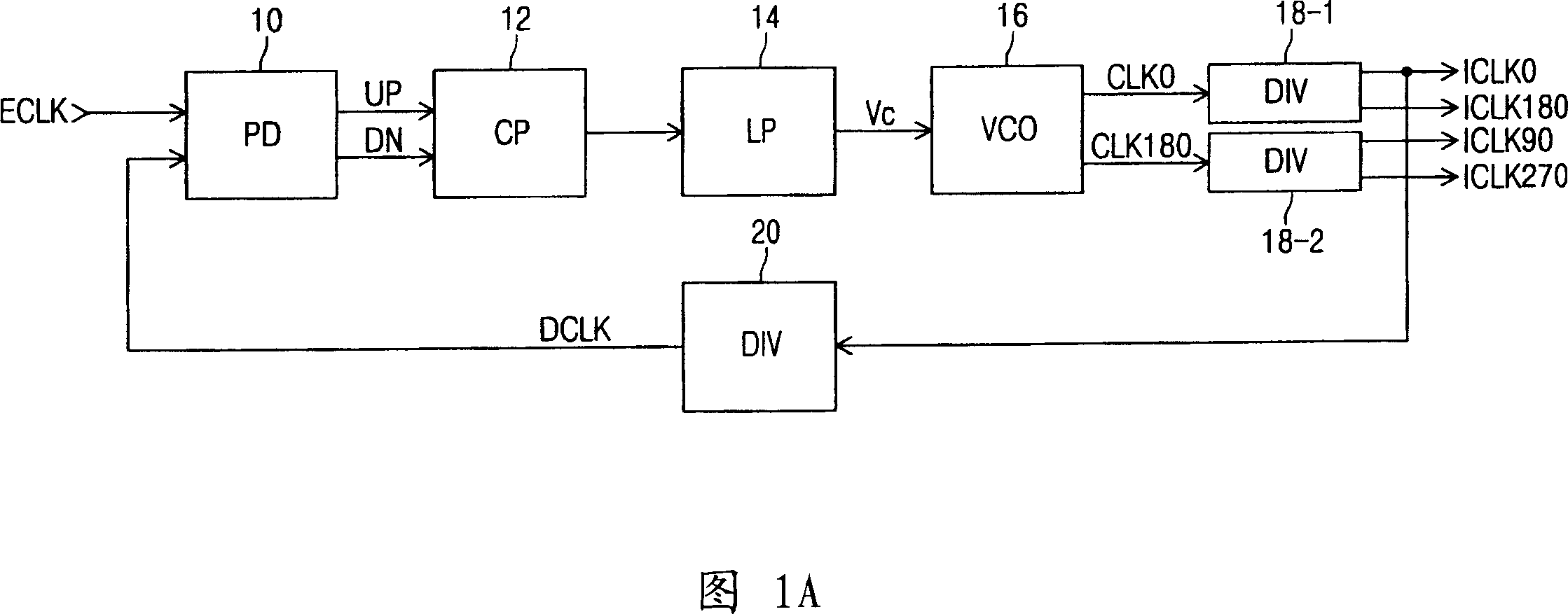
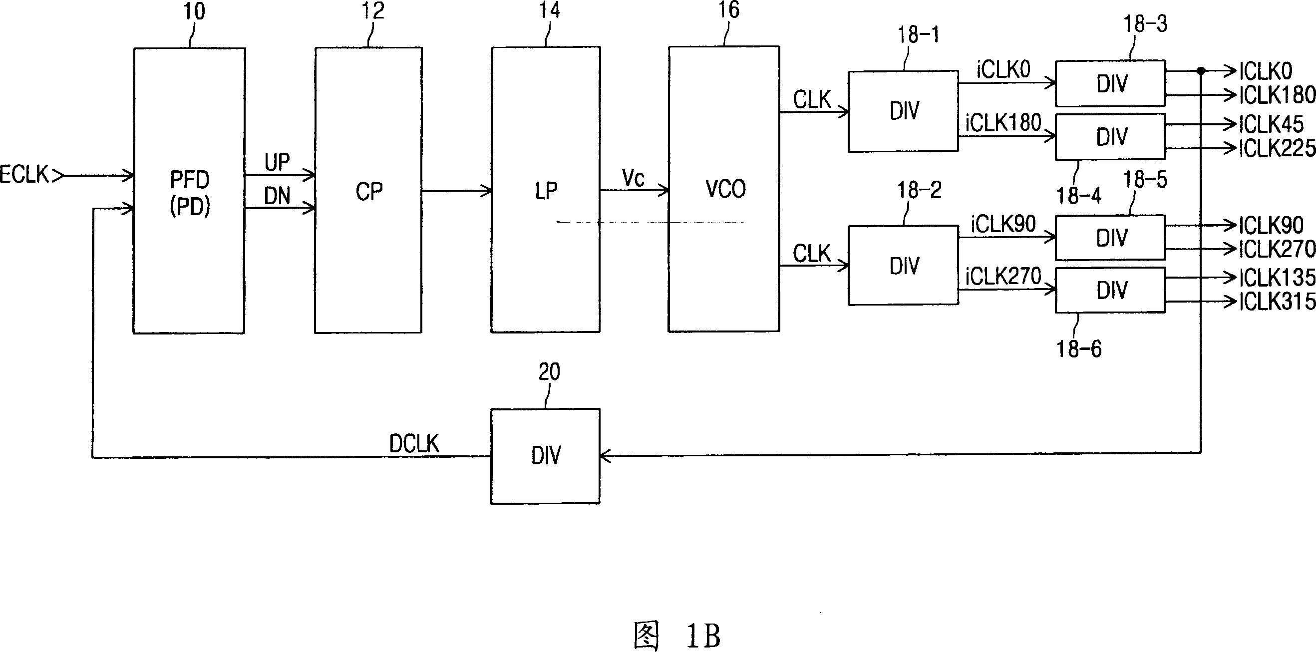
technical field [0001] The invention relates to a clock generation circuit and method for generating clock signals. Background technique [0002] Figure 1A illustrates a conventional phase-locked loop, which includes a phase detector (PD) 10, a charge pump (CP) 12, a loop filter (LP) 14, a voltage-controlled oscillator (VCO) 16, one or more frequency dividers 18-1, 18-2, and / or one or more frequency dividers 20. [0003] A phase detector (PD) 10 receives an external clock signal ECLK and generates an UP or DN signal in response to a phase difference between the external clock signal ECLK and a feedback clock signal DCLK. When the phase of the external input signal ECLK is ahead of the phase of the feedback clock signal DCLK, the UP signal is activated. The DN signal is activated when the phase of ECLK lags behind that of DCLK. [0004] Charge pump (CP) 12 and / or loop filter (LP) 14 increase the level of control voltage Vc in response to an activated UP signal and decrease...

Claims


Application Information

Patent Timeline
Patent Type & Authority Applications(China)
IPC IPC(8): H03K3/01H03K3/011H03K3/012H03K3/027H03L7/08G06F1/04
CPCH03K5/151H03L7/0814G06F1/04H03K5/133H03K5/1504H03L7/0812H03L7/0891H03L7/0816H03L7/0818H03L7/08
Inventor 金圭现
Owner SAMSUNG ELECTRONICS CO LTD
Features
  • R&D
  • Intellectual Property
  • Life Sciences
  • Materials
  • Tech Scout
  • Unparalleled Data Quality
  • Higher Quality Content
  • 60% Fewer Hallucinations
Learn More