Method for controlling an offset between two stops and tool for controlling an offset between two stops

a technology of offset and tool, which is applied in the direction of direct reading rulers, mechanical depth measurements, measurement gauges, etc., can solve the problems of no tool enabling simple, reliable and practical offset control, and achieve the effect of simple and efficient control

Active Publication Date: 2018-08-21
AIRBUS OPERATIONS (SAS)
View PDF12 Cites 4 Cited by
  • Summary
  • Abstract
  • Description
  • Claims
  • Application Information

AI Technical Summary

Benefits of technology

[0015]This tool makes it possible to simply and efficiently control if the offset is less than or equal to a tolerance value.

Problems solved by technology

According to the prior art, there is no tool enabling a simple, reliable and practical control of the offset.

Method used


Image

  • Method for controlling an offset between two stops and tool for controlling an offset between two stops
  • Method for controlling an offset between two stops and tool for controlling an offset between two stops
  • Method for controlling an offset between two stops and tool for controlling an offset between two stops

Examples


Embodiment Construction

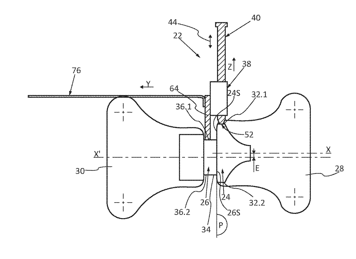
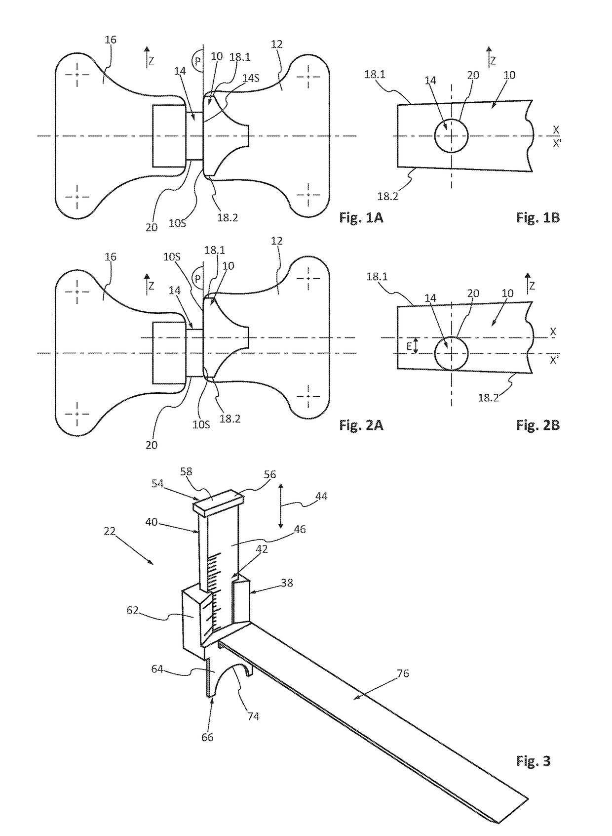
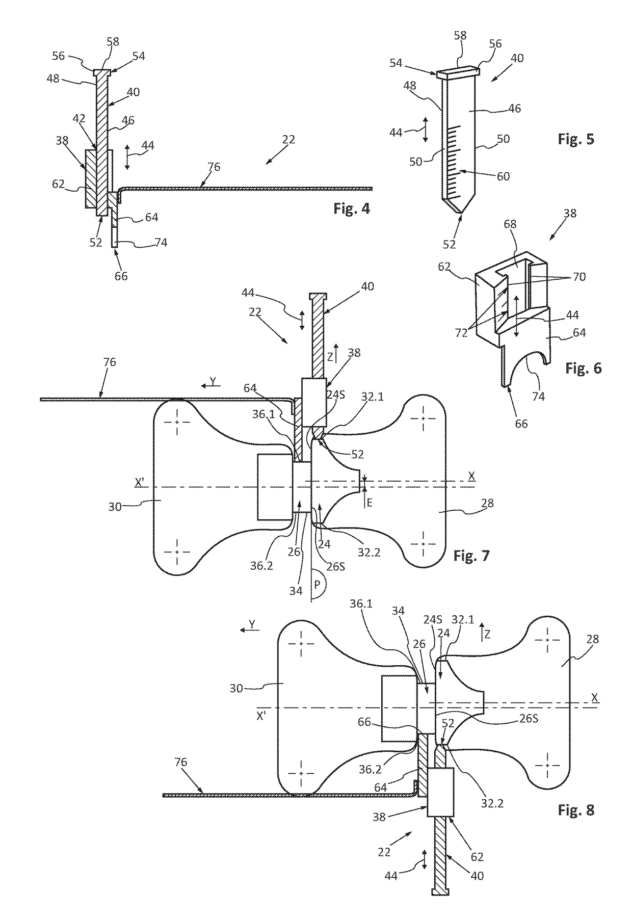
[0040]In FIGS. 3, 4, 7 and 8, item 22 represents a tool for controlling an offset between a first stop 24 and a second stop 26. The first and second stops 24 and 26 are approximately aligned in a Y-direction of offset.

[0041]According to a configuration, the first stop 24 is integral with a support 28 connected to a frame of an aircraft and the second stop 26 is integral with a support 30 connected to a door hinged relative to the frame.

[0042]The first stop 24 and the second stop 26 comprise a first contact surface 24S and a second contact surface 26S, respectively, configured to be in contact against one other when the door is in the closed position.

[0043]The first and second contact surfaces 24S and 26S are substantially planar and their contact plane is referred to as reference plane P. The reference plane P is substantially perpendicular to the Y-direction of offset.

[0044]According to an embodiment, the first contact surface 24S is elongated in shape. Thus, the first contact surf...


PUM


Abstract

A tool for controlling an offset between two stops, includes: a body which includes an extension with an end configured to abut against one of the stops, a sliding rule that is configured to slide in a longitudinal direction in relation to the body and which has an end configured to bear against the other stop, the sliding rule being shifted in a transversal direction in relation to the extension, and a system configured to control the displacement of the sliding rule in relation to the body.

Description

FIELD OF THE INVENTION[0001]The present invention relates to a method for controlling an offset between two stops and a tool for controlling an offset between two stops.BACKGROUND OF THE INVENTION[0002]FIGS. 1A, 1B, 2A and 2B represent a first stop 10 integral with a first support 12 connected to a frame and a second stop 14 integral with a second support 16 connected to a door hinged relative to the frame.[0003]The first stop 10 and the second stop 14 have a first contact surface 10S and a second contact surface 14S, respectively, these contact surfaces 10S and 14S being configured to be in contact against one other when the door is in the closed position.[0004]The first and second contact surfaces 10S and 14S are substantially planar and their contact plane is hereinafter referred to as the reference plane P.[0005]According to one configuration, the first contact surface 10S has an elongated shape delimited by a first edge 18.1 and second edge 18.2. The first and second edges 18.1...

Claims


Application Information

Patent Timeline
Patent Type & Authority Patents(United States)
IPC IPC(8): G01B3/20
CPCG01B3/20G01B3/08G01B5/18
Inventor MORILLE, DOMINIQUEMASSONNET, MAXIME
Owner AIRBUS OPERATIONS (SAS)
Why Eureka
Try Eureka