
Visualization system for three-dimensional images

a visualization system and image information technology, applied in the field of stereoscopic visualization of image information, can solve the problems of differing distances from the three-dimensional object visualized using the display device as perceived by an observer, and achieve the effect of improving visual comfor

Inactive Publication Date: 2018-10-23
CARL ZEISS VISION INT GMBH
View PDF25 Cites 0 Cited by
  • Summary
  • Abstract
  • Description
  • Claims
  • Application Information

AI Technical Summary

Benefits of technology

[0006]It is an object of the invention to permit an observer to visualize three-dimensional image information with improved visual comfort.
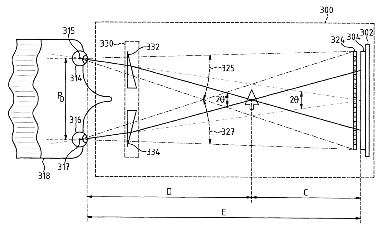
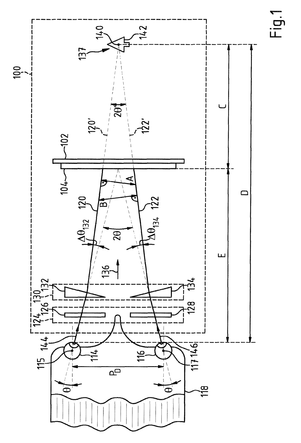
[0008]The invention is based here on the concept that an observer can observe a three-dimensional object visualized using the system with high vision comfort if the vision aid is used to adjust a stereo angle for the eyes that substantially corresponds to the stereo angle at which the display area of the display device visualizing the three-dimensional object is naturally viewed. In particular, one concept of the invention lies in that if, for the deviation of the intersection of the left and right observation beam paths which are extrapolated to infinity, the position corresponds to a three-dimensional object structure displayed using the display device, a pleasant, relaxed viewing of the object structure is made possible for the observer.
[0014]It is advantageous if the optical assembly is configured to be adjustable and enables variation of the courses of the left and right observation beam paths between the display area and the left and right eyes. An observer can then perceive, at various distances from the display area, stereoscopic image information with a three-dimensional visual impression. Another concept of the invention is the integration of the optical assembly in the vision aid.
[0016]It is advantageous if the vision aid is to this end connected to a control device with which the distance of the location in the left and right observation beam paths from the display area, at which the perpendicular distance between the left observation beam path, which is extrapolated to infinity, and the right observation beam path, which is extrapolated to infinity, is at a minimum, can be adjusted in dependence on the image information displayed on the display device. In this manner, relaxed perception of the image information is made possible in particular in the case of a three-dimensional structure moving in the space. One particular idea of the invention is to adjust the horizontal prismatic effect (P132,P134) of the vision aid in the left and right observation beam paths as follows:
[0018]One idea of the invention in particular is to configure the vision aid in the system for visualizing three-dimensional image information in the form of spectacles. Advantageously, the spectacles contain spectacle lenses having a mutually opposite prismatic effect. Since the horizontal prismatic effect of the spectacle lenses can be adjusted, it is possible for an observer to view three-dimensional structures on a display area in a relaxed manner, the deviation of which from the display area being variable. In order to enable relaxed viewing of three-dimensional structures at various distances from the display area, it is advantageous if a distance meter coupled to the control device is integrated in the spectacles so as to use it to adjust the prismatic effect of the spectacle lenses and advantageously their refractive powers or other optical parameters in dependence on the distance of the eyes of the observer from the display area.

Problems solved by technology

Known systems for visualization of three-dimensional image information face the problem that the distance from a three-dimensional object visualized using the display device as perceived by an observer differs from the distance of the observer eye from that focal plane on which the observer eye is accommodated.
In many people, this circumstance causes a state of physical discomfort, in particular dizziness.

Method used


Image

  • Visualization system for three-dimensional images
  • Visualization system for three-dimensional images
  • Visualization system for three-dimensional images

Examples


Embodiment Construction

[0029]FIG. 1 shows a system 100 for stereoscopic visualization of image information. The system 100 has a display device 102 having a display area 104. The display device 102 contains a dual-layer LCD display. Such a dual-layer LCD display can have a construction which corresponds to the LCD displays described in detail by way of figures in United States patent application publication 2006 / 0203338 A1. For the construction of the dual-layer LCD display in the display device 102, full reference is therefore made to the relevant disclosure of United States patent application publication 2006 / 0203338 A1 which is incorporated herein by reference.

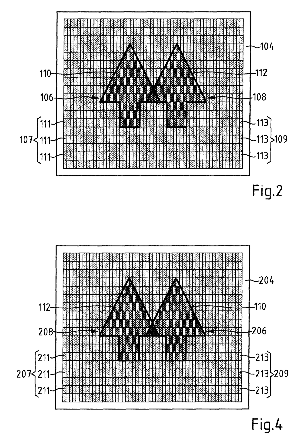
[0030]FIG. 2 shows the display area 104 of the display device 102 in plan view. The display device 102 generates a left stereoscopic partial image 106 and a right stereoscopic partial image 108 in the display area 104. The left partial image 106 is built with a first group 107 of display zones 111 with image points 110 of the dual-layer LCD displ...


PUM


Abstract

A system for stereoscopic visualization of image information includes a display device defining a display area for displaying a left and a right partial image. The display device displays the left partial image to a left eye of an observer focused on the display area in a first viewing direction using a left observation beam path and the right partial image to the right eye in a second viewing direction using a right observation beam path. The system includes a vision assist through which the left and right observation beam paths pass. The vision assist sets a beam course for the left and right viewing observation beam paths wherein, starting from the left and right eyes in a direction toward the display area, a perpendicular distance between the left and right observation beam paths decreases to a minimum at a finite distance from the display surface.

Description

CROSS REFERENCE TO RELATED APPLICATIONS[0001]This application is a continuation application of international patent application PCT / EP2013 / 054543, filed Mar. 6, 2013, designating the United States and claiming priority from German application 10 2012 205 271.2, filed Mar. 30, 2012, and the entire content of both applications is incorporated herein by reference.FIELD OF THE INVENTION[0002]The invention relates to a system for stereoscopic visualization of image information. The system has a display device having a display area for displaying a left and right partial image. The display device provides the left partial image to a left eye of an observer focused on the display area in a first viewing direction using a left observation beam path. The right partial image is displayed by the display device to a right eye of the observer focused on the display area in a second viewing direction using a right observation beam path. The system contains a vision aid through which the left and / ...

Claims


Application Information

Patent Timeline
Patent Type & Authority Patents(United States)
IPC IPC(8): G02B27/22G02B27/26G02C7/08G02C7/12G02C7/14G02B30/25G02B30/27
CPCG02B27/2228G02B27/2214G02B27/2242G02C7/14G02B27/26G02C7/083G02C7/12G02B27/2264G02B30/25G02B30/27G02B30/30G02B30/24G02B30/34G02B30/36
Inventor PACHER, PETERSESSNER, RAINER
Owner CARL ZEISS VISION INT GMBH
Learn More