Systems and methods for augmented reality

a technology of augmented reality and systems, applied in the field of methods, systems and devices for augmented reality, can solve the problems that the lenses are not suitable for all wearers, and achieve the effect of improving visual comfort and enhancing experien

Active Publication Date: 2019-02-12
ESSILOR INT CIE GEN DOPTIQUE
View PDF14 Cites 2 Cited by
  • Summary
  • Abstract
  • Description
  • Claims
  • Application Information

AI Technical Summary

Benefits of technology

[0005]Thus, ametropic wearers using a head-mounted display device require that the device comprise eyeglasses lenses that provide for enhanced visual comfort for both situations of ‘natural’ vision and ‘virtual’ vision.
[0014]The systems, methods and devices of the invention provide improved visual comfort for the ametropic wearer equipped with a head-mounted display device, so that the wearer's experience is enhanced for both ‘natural’ vision of the ‘real life’ world and ‘virtual’ vision of the information content provided by the device.

Problems solved by technology

However, these types of lenses are not suitable for all wearers.

Method used


Image

  • Systems and methods for augmented reality
  • Systems and methods for augmented reality
  • Systems and methods for augmented reality

Examples


example 1

ted Display Device

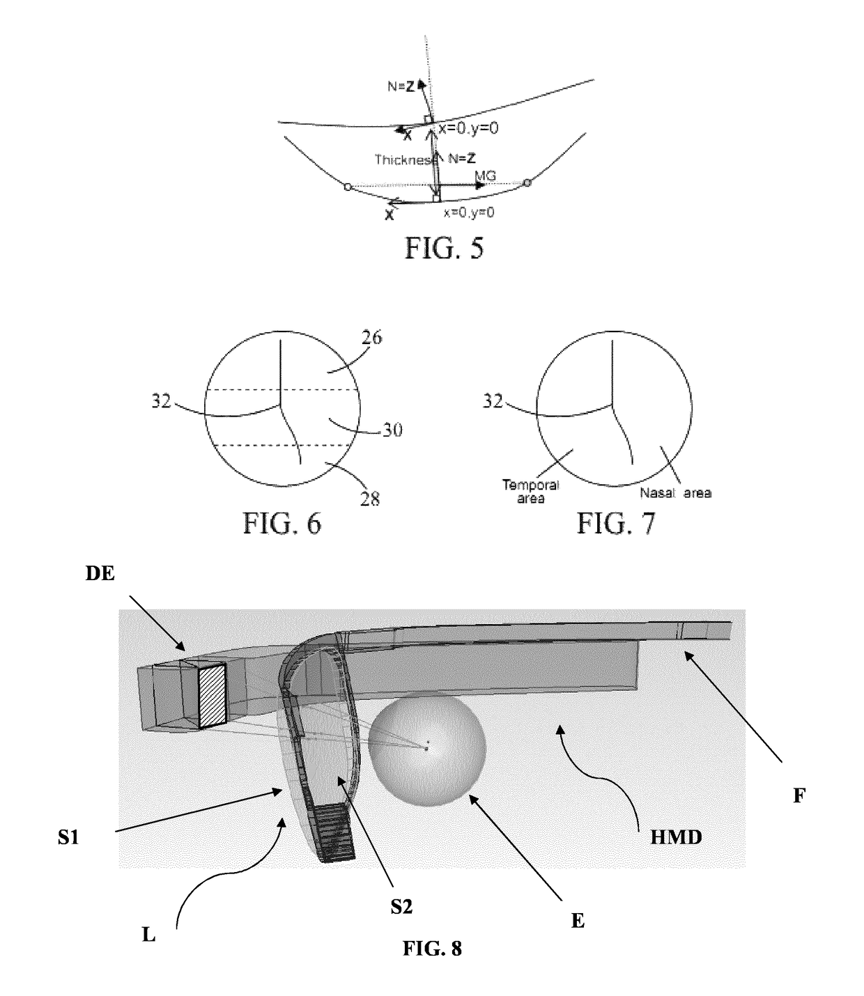
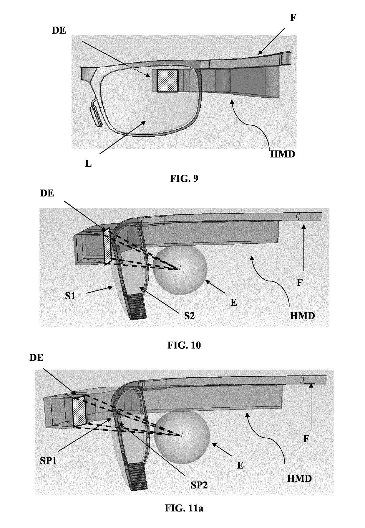
[0268]FIGS. 8-9 illustrate an exemplary HMD. The HMD comprises a frame F and a display element DE. It also comprises a lens L with object-side surface S1 and eye-side surface S2. The figures show the relative position of the eye E, the lens L and the display element DE.

[0269]FIGS. 10 and 11a-11b illustrate two different configurations for the HMD. The distance between the HMD and the eye is shorter in the HMD of FIG. 10 than on that of FIG. 11a. Dashed lines show possible ray tracing for the determination of the zone of stabilized optical performance (virtual vision, stabilized optical properties). FIGS. 11b and 12 show sub-parts SP1, SP2.

example 2

[0270]Lenses are designed for the following prescription values (P, Asti)=(6.00, 0.00), The following methods are implemented for lens design:[0271]no optimization (NO OPTIM);[0272]first method with target-mediated optical optimization (OPTIM1);[0273]second method with target-mediated optical optimization (OPTIM2);[0274]third method with surface combination (OPTIM3).

[0275]No OPTIM[0276]rear lens surface is spherical and designed to reach desirable prescription at optical center of the lens;[0277]the lens is analyzed in wearing condition[0278]the area of lens useful for virtual vision (zone of stabilized optical performance) has optical power and astigmatism defects of more than 0.5 D;[0279]at the optical center of the lens, there are also defects of optical power (0.06 D) and astigmatism (0.19 D).

[0280]Results are shown on FIG. 14.

[0281]OPTIM1[0282]lens is optimized in the desired areas, using target definition;[0283]optimization is carried out by ray tracing (wrap angle 7°, pantosc...

example 3

sion Lenses

[0297]Further lenses according to the invention are exemplified (FIGS. 30-38).

[0298]All results of Example 2 and 3 show that one or more of the following criteria C1; C2; C3 are met according to the invention:[0299]C1: The zone of stabilized optical performance (SP1, SP2) is arranged so that:[0300]said second sub-part (SP2) can be inscribed within a square of the eye-side surface (S2) having a length of side of 12-30° when measured as a distance in said (α,β) coordinates, with a, β expressed in degrees (°);[0301]said second sub-part (SP2) comprises a geometrical barycenter located on the eye-side surface (S2) of the lens in a location of the eye-side surface (S2) in a peripheral vision gaze direction; wherein the peripheral vision zone is defined as the set of gaze directions (αi,βi), with αi, βi expressed in degrees (°), such that SQRT(αi2+βi2)≥15°;[0302]it is stabilized in terms of optical power and / or unwanted astigmatism, so that over the entire zone, optical power an...


PUM


Abstract

Methods for augmented reality, and to lenses, systems and methods for improving visual comfort of a wearer equipped with a head-mounted device configured for display of information content.

Description

FIELD OF THE INVENTION[0001]The invention relates to methods, systems and devices for augmented reality.[0002]The invention relates more particularly to lenses and methods for improving the visual comfort of a wearer equipped with a head-mounted display device.BACKGROUND OF THE INVENTION[0003]Head-mounted display devices, such as ‘smart-glasses’, are known in the art. Such devices can allow a wearer to enjoy dual visualization: on the one hand, visualization of ‘real life’ objects by ‘natural’ vision; and on the other hand, visualization of ‘virtual’ items on a display. The ‘virtual’ items are generally computer-generated information content, such as text, images, etc.SUMMARY OF THE INVENTION[0004]For an ametropic wearer, visualization of ‘real life’ objects requires correction. This can be achieved with prescription ophthalmic lenses that are designed to correct the wearer's sight defects so that the wearer enjoys optimal visual acuity. The ophthalmic lenses may advantageously be c...

Claims


Application Information

Patent Timeline
Patent Type & Authority Patents(United States)
IPC IPC(8): A61B3/10G02C7/02G02C13/00G02C7/08G02B27/01
CPCG02C7/027G02B27/017G02C7/024G02C7/025G02C7/028G02C13/005G02C13/003G02C7/088G02B2027/011G02B2027/014G02B2027/0123G02B2027/0178G02C7/061
Inventor GUILLOT, MATTHIEUCOLAS, PAULINEFRICKER, SEBASTIENROUSSEAU, BENJAMIN
Owner ESSILOR INT CIE GEN DOPTIQUE
Why Eureka
Try Eureka