
Spectacle ophthalmic lens, method for determining a spectacle ophthalmic lens

a technology of ophthalmic lenses and spectacles, applied in the field of spectacle ophthalmic lenses, can solve the problems that wearers may not be fully satisfied by known ophthalmic lenses, and achieve the effects of improving comfort, enhancing visual comfort, and improving comfor

Active Publication Date: 2020-01-28
ESSILOR INT CIE GEN DOPTIQUE
View PDF7 Cites 0 Cited by
  • Summary
  • Abstract
  • Description
  • Claims
  • Application Information

AI Technical Summary

Benefits of technology

The present invention relates to a new type of eye glass lens that can correct a wearer's vision. The lens has two different zones - one in front of the wearer's eye and one in the back. The front surface has a special function that can make objects appear larger or smaller, depending on the needs of the wearer. The back surface helps to compensate for any distortion caused by the front surface. This lens design allows for better comfort and a more customized view for the wearer.

Problems solved by technology

The inventors have noticed that wearers may be not fully satisfied by known spectacle ophthalmic lenses.

Method used


Image

  • Spectacle ophthalmic lens, method for determining a spectacle ophthalmic lens
  • Spectacle ophthalmic lens, method for determining a spectacle ophthalmic lens
  • Spectacle ophthalmic lens, method for determining a spectacle ophthalmic lens

Examples


example 1

Progressive Lens with a Front Progressive Surface and a Back Progressive Surface According to the Present Invention

[0136]The lens of Example 1 has both a front progressive surface and a back progressive surface.

[0137]The prescribed sphere SPHp is 0 Diopter.

[0138]The prescribed astigmatism value CYLp is 0 Diopter and a prescribed axis AXISp is 0.

[0139]The prescribed addition Addp is 2 Diopter.

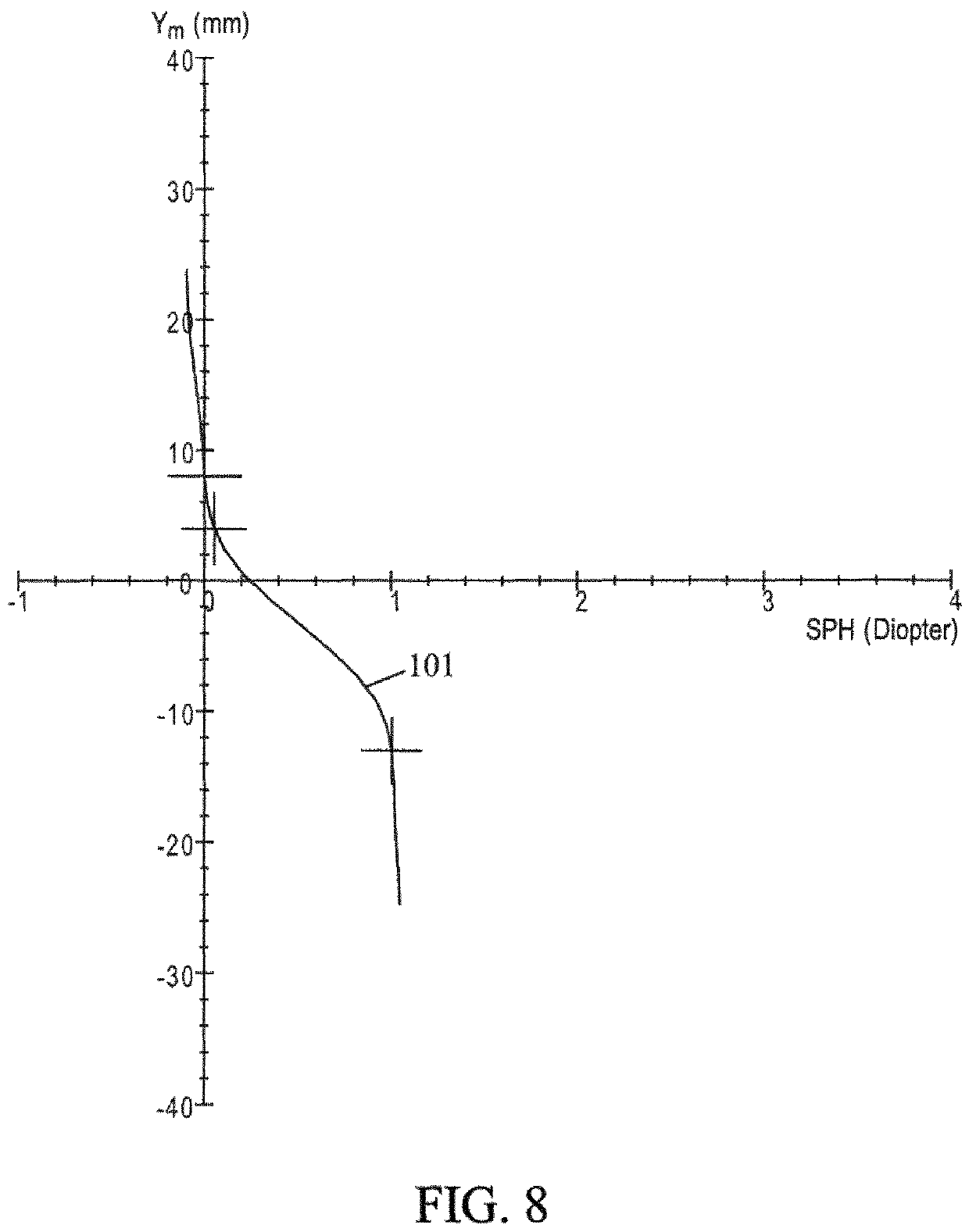
[0140]FIGS. 8 to 16 give optical and surface characteristics of the lens of Example of 1;

[0141]FIG. 8 shows the mean sphere variation SPHmean (xm_FS, ym_FS), curve 101, along the meridian line (xm_FS, ym_FS) of the front surface of the lens; the axis ym on the figure refers to a line where x=xm_FS and ym_FS varying from top to down according to the (x,y) referential of the front surface;

[0142]FIG. 9 shows the mean sphere iso-lines (0.25 Diopter between two neighbouring lines) on the front surface of the lens, according to the (x,y) referential of the front surface;

[0143]FIG. 10 shows the cylinde...

example 2

Progressive Lens with a Front Regressive Surface and a Back Progressive Surface According to the Present Invention

[0162]The lens of Example 2 has a front regressive surface and a back progressive surface. The prescribed sphere SPHp is 1 Diopter.

[0163]The prescribed astigmatism value CYLp is 0 Diopter and a prescribed axis AXISp is 0. The prescribed addition Addp is 2 Diopter.

[0164]FIGS. 17 to 25 give optical and surface characteristics of the lens of Example of 2;

[0165]FIG. 17 shows the mean sphere variation, SPHmean (xm_FS, ym_FS), curve 201, along the meridian line (xm_FS, ym_FS) of the front surface of the lens;

[0166]FIG. 18 shows the mean sphere iso-lines (0.25 Diopter between two neighbouring lines) on the front surface of the lens, according to the (x,y) referential of the front surface; the axis ym on the figure refers to a line where x=xm_FS and ym_FS varying from top to down according to the (x,y) referential of the front surface;

[0167]FIG. 19 shows the cylinder iso-lines (...


PUM


Abstract

A spectacle ophthalmic lens having a front surface and a back surface, the spectacle ophthalmic lens including a nasal lateral zone and a temporal lateral zone, wherein the front surface includes a progressive or regressive front surface which provides at least a magnifying function in the nasal and / or the temporal lateral zone of the lens, and wherein the back surface substantially compensates dioptric effects of the magnifying function of the progressive or regressive front surface.

Description

FIELD OF THE INVENTION[0001]The invention relates to spectacle ophthalmic lenses and to a method for determining a spectacle ophthalmic lens.BACKGROUND OF THE INVENTION[0002]A wearer may be prescribed a positive or negative optical power correction. For presbyopic wearers, the value of the power correction is different for far-vision and near-vision, due to the difficulties of accommodation in near-vision. Ophthalmic lenses suitable for presbyopic wearers are multifocal lenses, the most suitable being usually progressive multifocal lenses.SUMMARY OF THE INVENTION[0003]The inventors have noticed that wearers may be not fully satisfied by known spectacle ophthalmic lenses.[0004]They have noticed that wearers may be sensitive distortions and may obtain an enhanced visual comfort when providing them a magnifying function; they have further noticed that visual comfort may be significantly enhanced when a magnifying function is provided in the nasal and / or the temporal lateral zone of the...

Claims


Application Information

Patent Timeline
Patent Type & Authority Patents(United States)
IPC IPC(8): G02C7/06G02C7/02
CPCG02C7/068G02C7/027G02C7/061
Inventor GUILLOUX, CYRIL
Owner ESSILOR INT CIE GEN DOPTIQUE
Learn More