
Method for determining an ophthalmic lens and associated ophthalmic lens

Active Publication Date: 2019-09-12
ESSILOR INT CIE GEN DOPTIQUE
View PDF0 Cites 2 Cited by
  • Summary
  • Abstract
  • Description
  • Claims
  • Application Information

AI Technical Summary

Benefits of technology

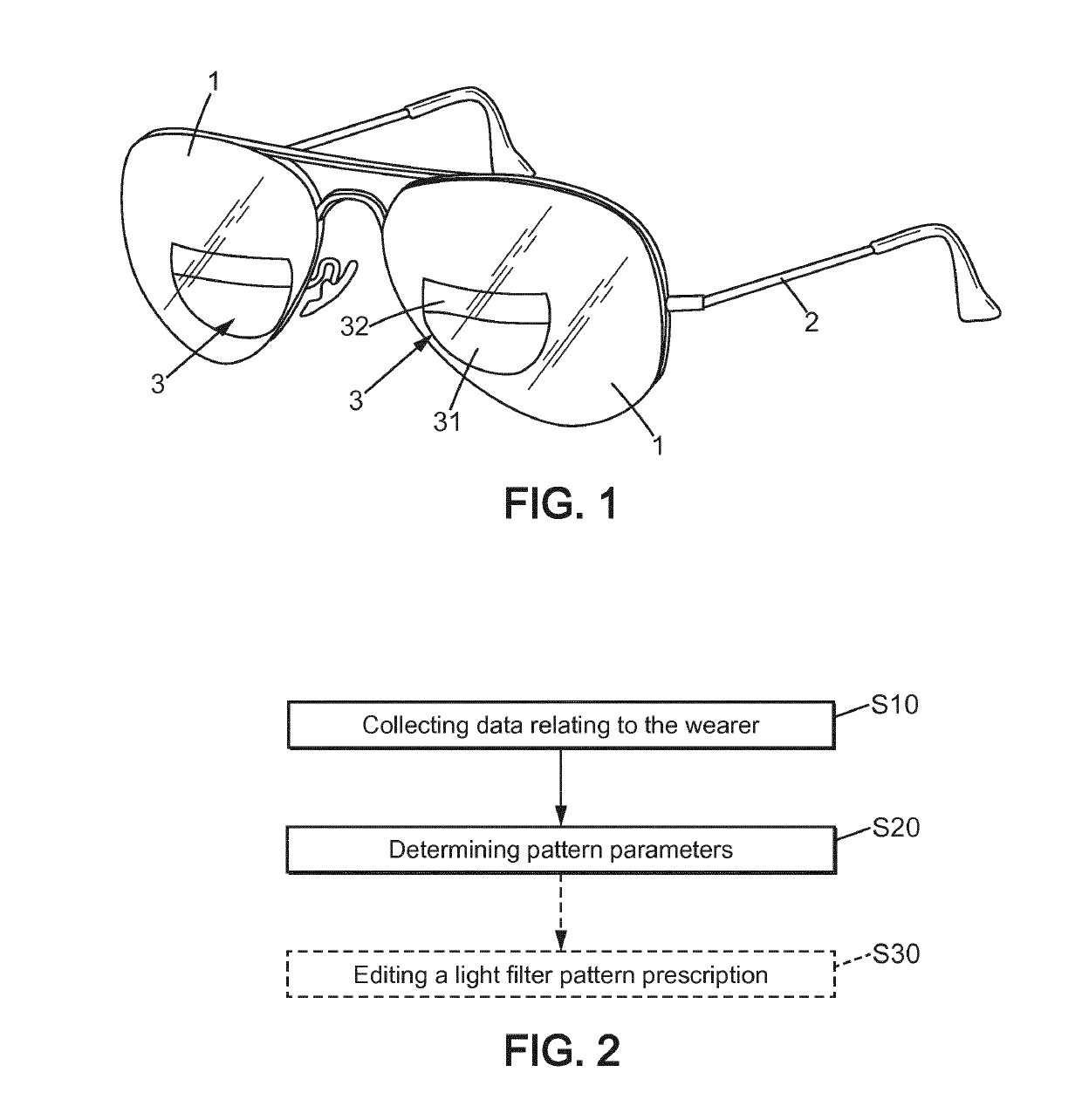
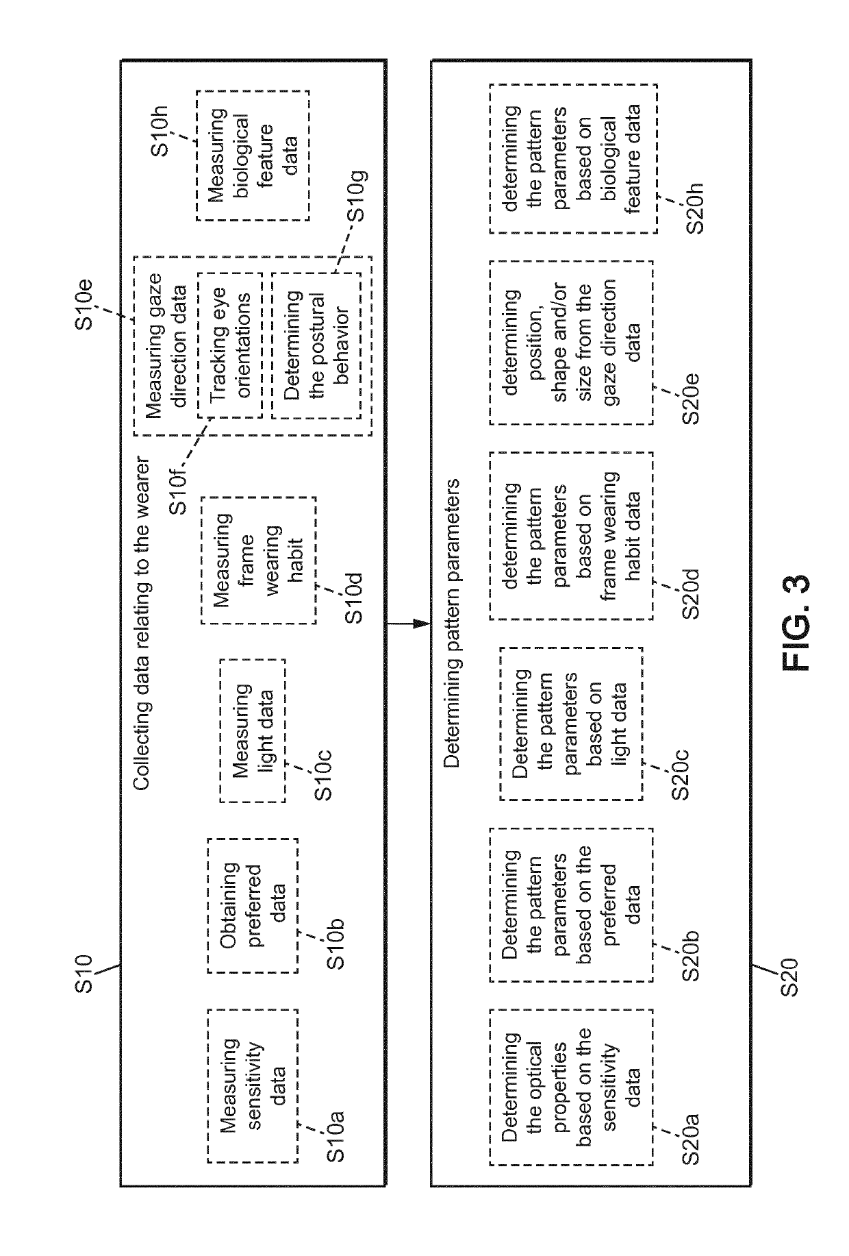
The invention provides a method for creating a personalized light-filter pattern for ophthalmic lenses that takes into account the specific needs and characteristics of the wearer. The method takes into account data relating to the wearer's physiological characteristics, visual, postural or oculomotor behavior, and other parameters that should be considered when determining a personalized light-filter pattern. The light-filter pattern is better adapted to the wearer, providing improved visual comfort. The position, shape, and size of the light-filtering zones can also influence the efficiency of the pattern. By measuring the amount of light received by the wearer, the pattern parameters can be adjusted to improve the visual comfort of the wearer in different lighting conditions and to ensure that the amount of light does not exceed a given value. The method also takes into account the morphology of the wearer, such as pupil size and distance, to create a more efficient light-filter pattern for that wearer.

Problems solved by technology

In other cases, the filter is more complex and adapted for particular activities such as piloting an airplane, outdoor activities such as fishing, golfing and hunting, driving at night, protection against blue light, etc.
However, the light-filter patterns of the prior art are usually designed based on data relating to a reference population and / or for a limited set of situations so that these light-filter patterns may not be adapted to the wearer, or for the specific activity and / or to the environment in which the ophthalmic lens with the light-filter pattern will be used, resulting in visual discomfort.

Method used


Image

  • Method for determining an ophthalmic lens and associated ophthalmic lens
  • Method for determining an ophthalmic lens and associated ophthalmic lens
  • Method for determining an ophthalmic lens and associated ophthalmic lens

Examples


example 2

A Progressive Ophthalmic Lens Adapted for New Progressive Lens Wearers or for Vision Stabilization

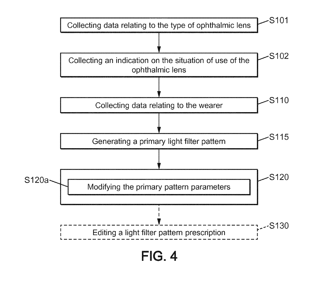
[0113]In step S115a, a clear progressive lens defined by a design of the correction properties is selected based on the wearer's prescription D2 and the basic intended purpose D4.

[0114]In step S115b, a primary filter pattern comprising first, second and third light-filtering zones respectively corresponding to the far field zone, the near field zone and the transition zone, is generated based on the progressive lens design choice and the frame size. A fourth primary light-filtering zone corresponding to the zone outside of the first to third light-filtering zones is also generated. The optical properties of the first to third primary light-filtering zones are set to be at a predetermined value corresponding to a high transmission of light for all wavelengths. The optical properties of the fourth primary light-filtering zone is set to be at a predetermined value corresponding to a low tr...

example 3

Ophthalmic Lens Adapted for Night Driving

[0116]In step S115a, a type of ophthalmic lens is selected based on the basic intended purpose D4, the correction properties D5 and optionally, on the type and / or size of the frame, design of correction properties and a type of tint.

[0117]In step S115b, a primary filter comprising five primary light-filtering zones. The size, position and shape of each of the five primary light-filtering zones are determined based on the average positions of the view field of a standard population looking at the each of the two side mirrors, the rear mirror, the instrument panel and straight forward through the ophthalmic lens that is used when the wearer is looking at the road is generated, respectively.

[0118]In step S120, the wearer is seated in a car or is looking at a virtual scene representing the_environment of the car, for example using a virtual reality headset or a display. The wearer is asked to perform the five following tasks: look at the left sid...

example 4

Ophthalmic Lens Adapted for Daylight Driving

[0119]In step S115a, a type of ophthalmic lens is selected based on the basic intended purpose D4, the correction properties D5 and optionally, on the type and / or size of the frame, design of correction properties.

[0120]In step S115b, a primary filter comprising two primary light-filtering zones are generated. The shape, size and position of the first primary light-filtering zone are determined based on the average position of the upper part of the scene corresponding to the viewing field through the windshield and to the reflective dashboard. The optical properties of the first primary light-filtering zone are set to correspond to a polarizing filter whose polarization axis is set to attenuate reflection on the road or on the reflective dashboard. The second primary light-filtering zone corresponds to the complementary part of the first primary light-filtering zone on the ophthalmic lens. The optical properties of the second primary light...


PUM


Abstract

A method for determining an ophthalmic lens (1) for a wearer with a personalized light-filter pattern (3) defined by pattern parameters, wherein the method comprises collecting data relating to the wearer and determining the pattern parameters based on the data relating to the wearer.

Description

FIELD OF THE INVENTION[0001]The present invention relates to a method for determining an ophthalmic lens for a wearer with a personalized light-filter pattern and to an ophthalmic lens with a personalized light-filter pattern.BACKGROUND OF THE INVENTION[0002]Light filters like sunglasses or uniformly tinted glasses are used to improve the visual comfort of the wearer in a particular situation, for example while performing sunny outdoor activities, working in front of a computer or watching TV. These light filters are usually coated layers on an ophthalmic lens to filter off harmful ultraviolet light, high-energy visible light and / or infrared light.[0003]To improve the wearer's visual comfort, more complex filters are used. The visual comfort may be improved by introducing light-filtering zones at different positions on the ophthalmic lens, the light-filtering zones modifying the optical properties of the light coming through the ophthalmic lens up to the wearer's eye, when the weare...

Claims


Application Information

Patent Timeline
IPC IPC(8): G02C7/10G02C7/02
CPCG02C7/105G02C7/025G02C7/027
Inventor ANG, KER CHINNG, PAULYNPARMENTIER, VALÉRIEBOURDONCLE, BERNARDSCHERLEN, ANNE-CATHERINE
Owner ESSILOR INT CIE GEN DOPTIQUE
Learn More