Detachable hinge for glass frame

a technology of glass frame and hinge, which is applied in the direction of hinges, clear-view screens, ships, etc., can solve the problems of limiting the visibility of sailors and reducing the visibility of those who look through glass panels

Active Publication Date: 2018-11-13
VERALEX INC
View PDF25 Cites 4 Cited by
  • Summary
  • Abstract
  • Description
  • Claims
  • Application Information

AI Technical Summary

Benefits of technology

[0021]According to an embodiment, the core has a recess therein which, upon sliding the core with respect to the jacket, reaches a location where the blocker is housed in the jacket, the blocker retracting into the recess, thereby moving the blocker away from the inward edge, releasing the shaft from the second socketed member and allowing the first socketed member and the second socketed member to be separated.
[0028]According to an embodiment, the first socketed member is to be attached to the door and the second socketed member is to be attached to the stationary panel, the hinge providing hingeable movement between the door and the stationary panel, and removability of the door with respect to the stationary panel.
[0031]providing a shaft extending longitudinally, the shaft comprising a blocker which is extended about the shaft, the shaft having a first portion thereof, away from the blocker, secured to a first socketed member which is itself secured to any one of the door and the stationary panel, and a second portion thereof, comprising the blocker, housed within a lumen of a second socketed member, the lumen comprising a cavity larger than a remainder of the lumen and which defines an inward edge on which the blocker abuts, thereby retaining the shaft in the lumen;

Problems solved by technology

However, these door or window structures, once opened, either remain open, and thus, remain subject to moving between the closed position and the open position with the wind and other factors, or they lock in a completely opened position overlapping one or more adjacent glass panels, thereby reducing the visibility for those who look through the glass panels.
However, this configuration greatly limits the visibility of the sailor since the glass through which the person is expected to look is doubled.

Method used


Image

  • Detachable hinge for glass frame
  • Detachable hinge for glass frame
  • Detachable hinge for glass frame

Examples


Embodiment Construction

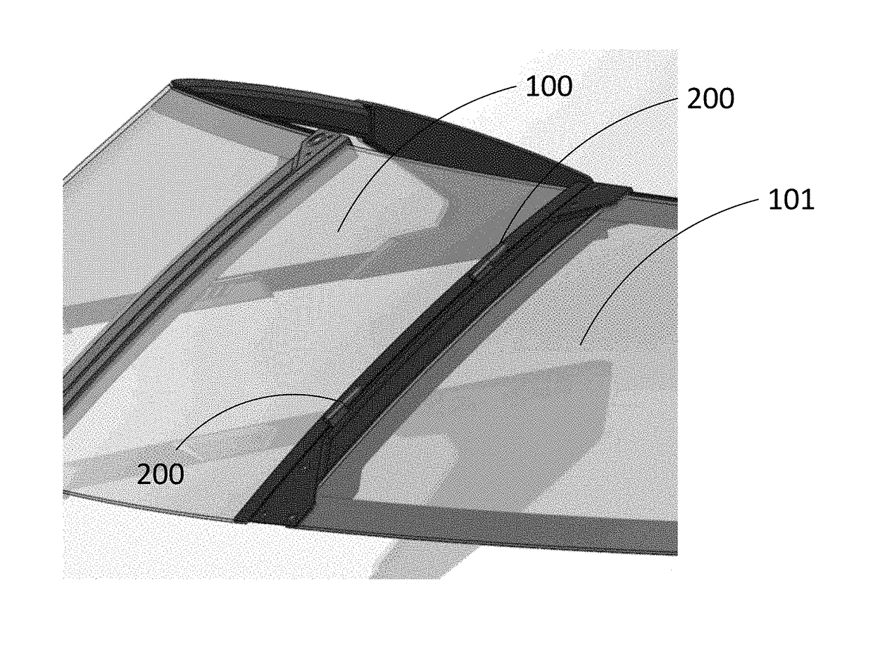
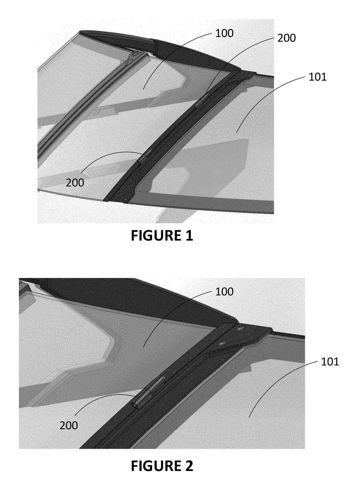
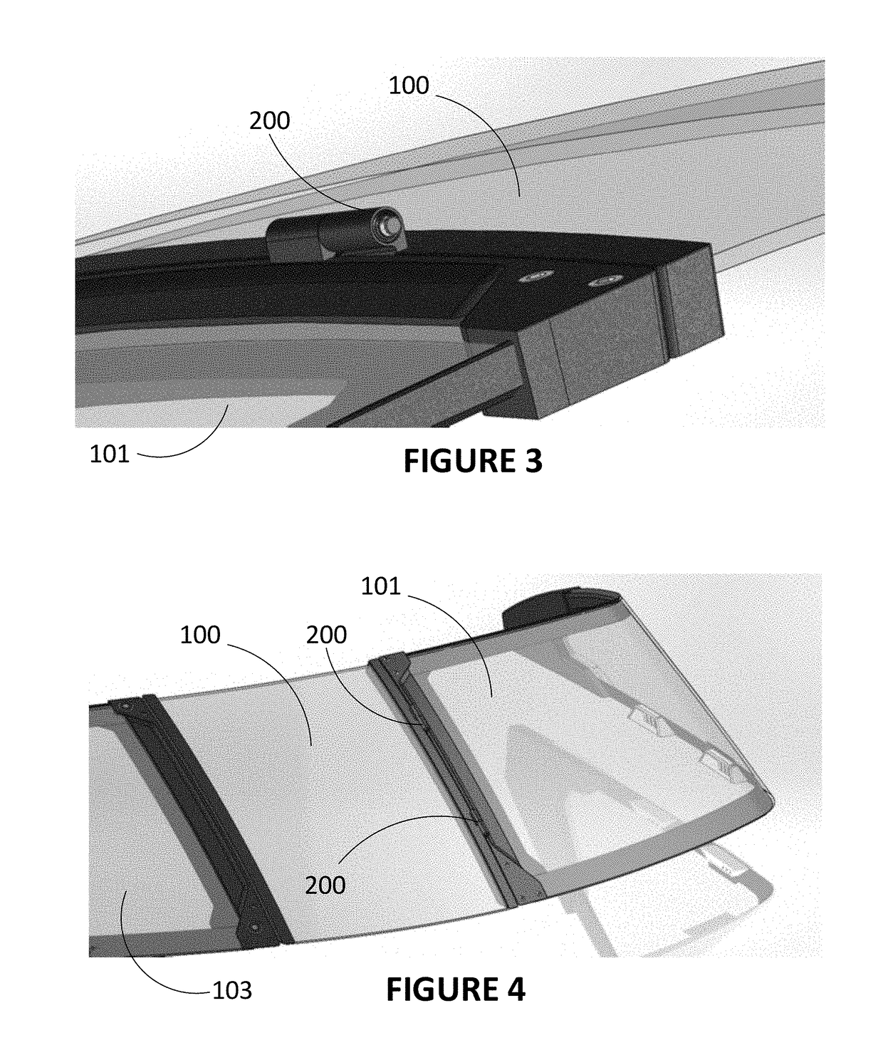
[0062]There is described a hinge for detachably connecting a door or window to a wall or a frame such as a windshield. The hinge comprising a shaft extending longitudinally, further comprising a blocker which is extendable about the shaft. A first socketed member is fixed to the shaft, and a second socketed member comprises a lumen for sliding the shaft therein. The lumen comprises a cavity larger than a remainder of the lumen and which defines an inward edge on which the blocker abuts, thereby retaining the shaft in the lumen. The shaft comprises an inner recess which can house the blocker therein if the inner recess is aligned with the blocker, thereby retracting the blocker from the cavity and releasing the shaft from the second socketed member and allowing the first socketed member and the second socketed member to be separated. This can be useful for detaching a door of a boat windshield, for example.

[0063]In an embodiment, there is described a door assembly system, or more pre...


PUM


Abstract

There is described a hinge for detachably connecting a door or window to a wall or a frame such as a windshield. The hinge comprising a shaft extending longitudinally, further comprising a blocker which is extendable about the shaft. A first socketed member is fixed to the shaft, and a second socketed member comprises a lumen for sliding the shaft therein. The lumen comprises a cavity larger than a remainder of the lumen and which defines an inward edge on which the blocker abuts, thereby retaining the shaft in the lumen. The shaft comprises an inner recess which can house the blocker therein if the inner recess is aligned with the blocker, thereby retracting the blocker from the cavity and releasing the shaft from the second socketed member and allowing the first socketed member and the second socketed member to be separated. This can be useful for detaching a door of a boat windshield, for example.

Description

CROSS REFERENCE TO RELATED APPLICATIONS[0001]This application claims priority from U.S. Provisional Patent Application No. 62 / 385,494 filed on Sep. 9, 2016 the content of which is incorporated by reference in its entirety.BACKGROUND(a) Field[0002]The subject matter disclosed generally relates to door hinges. More specifically, it relates to a detachable hinge for a glass frame.(b) Related Prior Art[0003]There exists in the market glass frames including one or more glass panels. Such frames are often provided as walls or wall extensions in buildings, or as stand-alone structures such as windshields for boats or the like.[0004]These glass frames are often configured to include one or more glass panels that open and close defining door or window structures. These door or window structures are hingedly connected to a wall or a portion thereof. However, these door or window structures, once opened, either remain open, and thus, remain subject to moving between the closed position and the...

Claims


Application Information

Patent Timeline
Patent Type & Authority Patents(United States)
IPC IPC(8): B63B19/02E05D7/10B63B9/00E05D5/12E05D3/02B63B19/00
CPCB63B19/02B63B9/00E05D3/02E05D5/121E05D7/1005E05D5/128E05Y2900/514B63B2019/0038E05D2005/122E05D2007/1033B63B71/00
Inventor DUBE, SIMON
Owner VERALEX INC
Why Eureka
Try Eureka