Arrangement for effecting movement of a wing tip device between a flight configuration and a ground configuration

a technology of wing tip device and flight configuration, which is applied in the field of aircraft, can solve the problems of effectively limited maximum aircraft span and technical challenges

Active Publication Date: 2018-11-27
AIRBUS OPERATIONS LTD
View PDF61 Cites 6 Cited by
  • Summary
  • Abstract
  • Description
  • Claims
  • Application Information

AI Technical Summary

Benefits of technology

[0009]The actuator may be coupled to the wing tip device at a coupling between the actuator and the wing tip device. The coupling may be referred to as an actuated location on the wing tip device. The actuator may be arranged such that the coupling, during movement of the wing tip device between the flight configuration and the ground configuration, follows a curved, and more preferably a substantially arcuate, locus. In some embodiments of the invention, the actuator may be a rotary actuator. In some other embodiments of the invention, the actuator need not be a rotary actuator but may nevertheless be arranged to effect arcuate motion of the coupling. For example, the actuator may comprise a linear actuator and a linkage mechanism, such as a rotating link. The arcuate locus preferably has a constant radius. Having the coupling follow a substantially arcuate locus may be particularly advantageous as it may result in a relatively simple and reliable actuation arrangement.
[0012]When the wing tip device is in the ground configuration, the relative locations of the pivot and the coupling, are preferably such that when the wing tip device is urged to undergo a rotation about the pivot, from that ground configuration, the reaction force at the coupling is substantially radial with respect to the arcuate locus. This arrangement has been found to be especially beneficial because it ensures there is a minimal component of the reaction force in a tangential direction, and therefore a minimal force seeking to back-drive the actuator. The wing tip device tends to therefore be relatively stable in the ground configuration. Furthermore, the need for locking / braking the actuator is reduced.
[0017]When the wing tip device is in the ground configuration, the stability of the wing tip may also be facilitated by other features. For example, the actuator may be non-back driveable. The carriage guide may be such that the wing tip device is held in a geometric lock when it is in the ground configuration.
[0023]According to another aspect of the invention there is provided a method of designing the path of movement of a wing tip device on the aircraft as described herein. The method comprises the steps of determining: (i) the radius of the arcuate locus, and / or (ii) the shape of the carriage guide and / or (iii) the relative positions of the pivot and the coupling, such that as the wing tip device moves along the carriage guide between the flight and the ground configurations, the movement of the wing tip device comprises a translational component of movement along the carriage guide, and rotational component about the pivot. By determining the appropriate radius, carriage guide shape, and / or relative positions of the pivot and coupling, the movement of the wing tip device may be controlled. For example, the relative locations of the pivot and coupling may determine the turning moment that the wing tip device is subjected to. The carriage guide shape may determine the path of the pivot.

Problems solved by technology

However, the maximum aircraft span is effectively limited by airport operating rules which govern various clearances required when manoeuvring around the airport (such as the span and / or ground clearance required for gate entry and safe taxiway usage).
There are technical challenges in providing a practical arrangement for providing such movement.
Amongst the issues to be addressed are: the problem of providing a safe and reliable arrangement to enable such movement without impacting unduly on the design of the wing; and the problem of providing a compact and lightweight drive to effect the movement of the wing tip device.

Method used


Image

  • Arrangement for effecting movement of a wing tip device between a flight configuration and a ground configuration
  • Arrangement for effecting movement of a wing tip device between a flight configuration and a ground configuration
  • Arrangement for effecting movement of a wing tip device between a flight configuration and a ground configuration

Examples


first embodiment

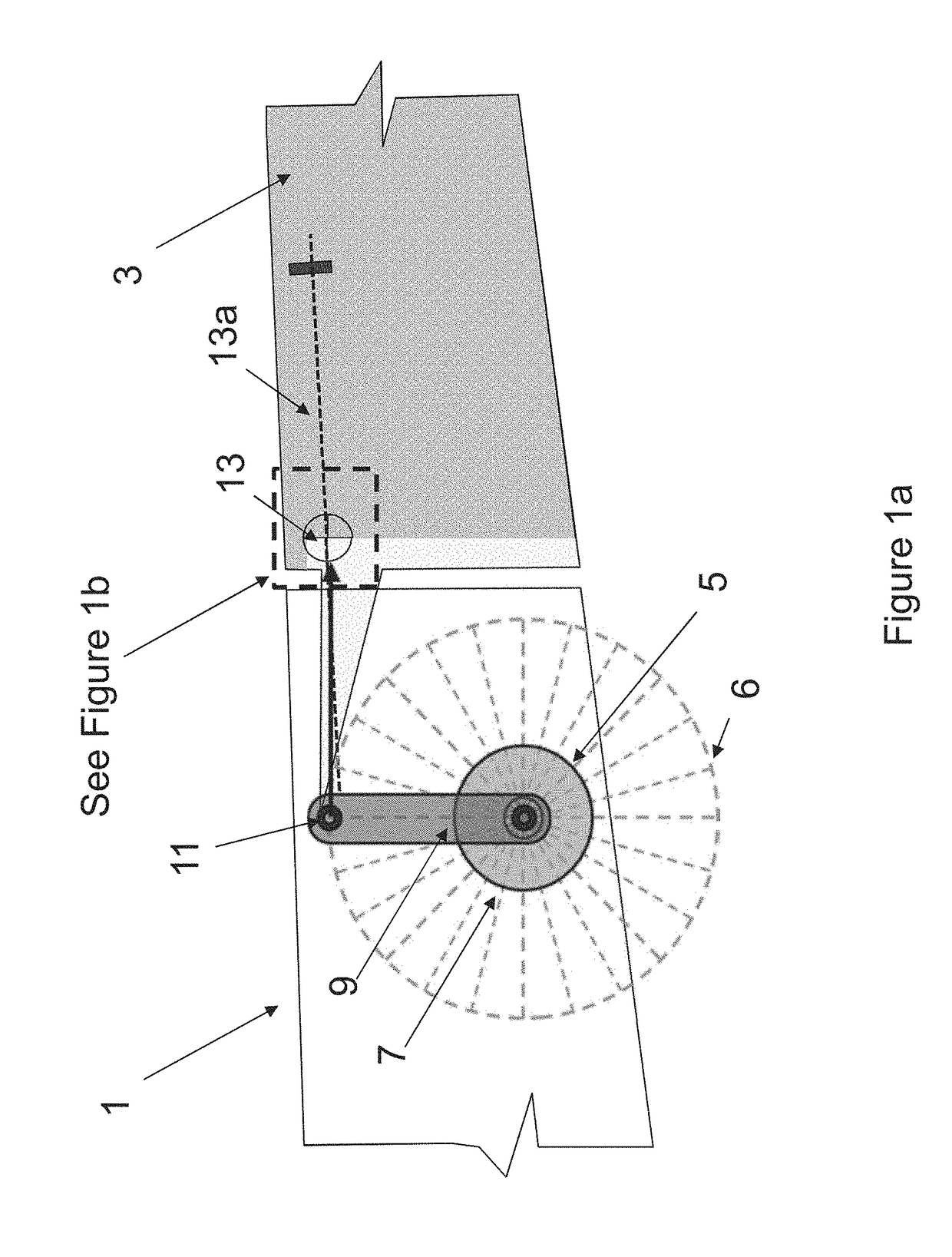
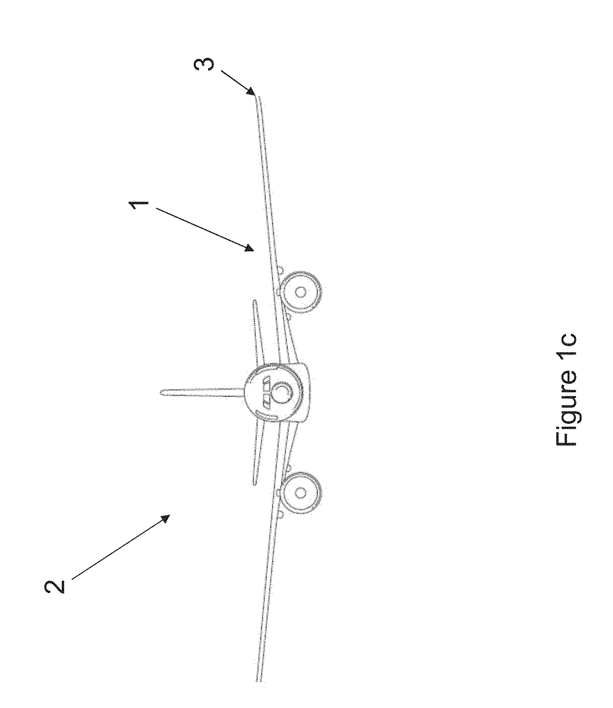
[0032]FIG. 1a shows a schematic side view of a wing 1 and wing tip device 3 according to the invention. The wing tip device 3 is in the form of a planar wing tip extension, but for the sake of clarity only the root portion of the wing tip extension is shown in FIG. 1a. The wing 1 and wing tip device 3 are on the aircraft 2 shown in FIG. 1c.

[0033]A rotary actuator 5 is housed in the wing 1 and comprises a motor 7 arranged to rotate a fixed-length link 9. The link 9 is coupled, at its distal end, to the wing tip device 3 at coupling 11. As will become apparent with reference to FIGS. 2a-h, the coupling 11 is an actuated location on the wing tip device 3, which follows an arcuate locus 6 of constant radius as the actuator 5 effects movement of the wing tip device 3. The arcuate locus is shown in dotted lines in FIGS. 1a, and 2a-2i.

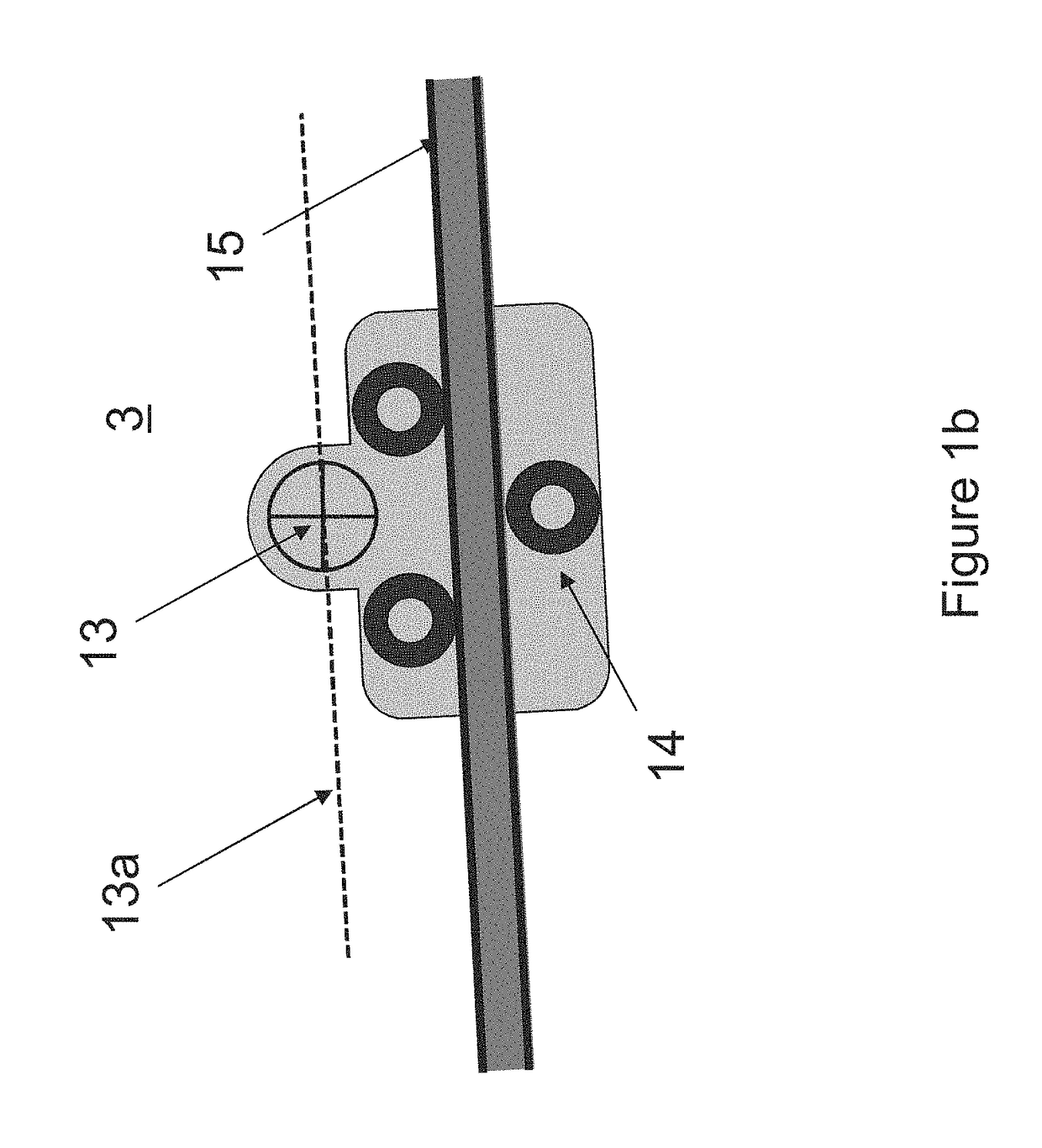
[0034]The wing tip device 3 is rotatable about a pivot 13. The locus 13a of the pivot 13, as the wing tip device 3 moves away from the flight configuration...

second embodiment

[0048]Firstly, rather than a planar wing tip extension, the wing tip device of the invention is an upwardly extending winglet 103. For clarity, only the root portion of the wing tip device 103 is shown in the Figures.

[0049]Secondly, the track assembly 115 (which mirrors the shape of the locus 113a) has a curved region, rather than being substantially straight along its length. This shape of track, together with the relative positions of the coupling 111 and the pivot 113, is particularly advantageous for the reasons set out below:

[0050]The start of the track (closest to the wing tip) comprises a straight portion inclined downwardly from the plane of the wing 101. As shown in FIGS. 3a and 3b, during the initial phase of motion away from the flight configuration (FIG. 3a) the wing tip device 103 translates along this straight portion. This translation has been found to be especially useful in terms of preserving the life of the sealing arrangement and in unlocking the wing tip device ...


PUM


Abstract

An aircraft comprises a wing, a wing tip device at the tip of the wing and an actuator. The actuator is arranged to effect movement of the wing tip device between a flight configuration for use during flight and a ground configuration in which the wing tip device is moved away from the flight configuration such that the span of the aircraft is reduced. The aircraft comprises a carriage guide, such as a track assembly, fixed relative to the wing, and a carriage arranged to move along the track assembly as the wing tip device moves between the flight and ground configurations. The carriage carries the wing tip device on a pivot, such that the wing tip device is rotatable relative to the carriage, about the pivot, as the carriage moves along the track assembly. The movement of the wing tip device between the flight and the ground configurations, may thereby comprise both a rotational component of movement of the wing tip device about the pivot, and a translational component of movement, of the pivot, along the track assembly.

Description

RELATED APPLICATIONS[0001]The present application claims priority from Great Britain Application Number 1502661.0, filed Feb. 17, 2015, the disclosure of which is hereby incorporated by reference herein in its entirety.BACKGROUND OF THE INVENTION[0002]The present invention relates to aircraft and more specifically, but not exclusively, to passenger aircraft with wing tip devices.[0003]There is a trend towards increasingly large passenger aircraft, for which it is desirable to have correspondingly large wing spans. However, the maximum aircraft span is effectively limited by airport operating rules which govern various clearances required when manoeuvring around the airport (such as the span and / or ground clearance required for gate entry and safe taxiway usage).[0004]In some suggested designs, aircraft are provided with wing tip devices which may be folded to reduce the span of the aircraft on the ground (compared to when the aircraft is configured for flight). The wing tip devices ...

Claims


Application Information

Patent Timeline
Patent Type & Authority Patents(United States)
IPC IPC(8): B64C3/56B64C23/06
CPCB64C3/56B64C23/072Y02T50/164Y02T50/10B64C3/546B64C3/58
Inventor THOMPSON, ROBERT IAN
Owner AIRBUS OPERATIONS LTD
Why Eureka
Try Eureka