Apparatus for rowing in the direction the rower is facing

a technology of oar blades and oar blades, which is applied in the direction of waterborne vessels, propulsive elements, vessel construction, etc., can solve the problem that the rower cannot have any influence on the position of the oar blades, and achieve the effect of facilitating the feathering and squaring of the blades

Active Publication Date: 2019-01-01
BIERMA JOCHUM
View PDF5 Cites 1 Cited by
  • Summary
  • Abstract
  • Description
  • Claims
  • Application Information

AI Technical Summary

Benefits of technology

[0010]In order to facilitate the feathering and squaring of the blade of the oar lever as a result of the movement of the grip lever, the grip lever features a spring configuration that applies torque to the lever. Because opposing torques are required during feathering and squaring of the oar levers, a spring system is configured between the grip lever and the bearing body so that the line of action of the spring configuration intersects the axis of rotation of the grip lever when it is positioned half way between the two limit positions. As a consequence, when the grip lever is rotated so that its position of rotation crosses the line of action of the spring configuration, the direction of torque acting on the grip lever changes so that the spring configuration assists rotation into the desired limit position for feathering or squaring the oar blade.

Problems solved by technology

However, this automatic feathering and squaring of the oar blades as a function of the pivot movement of the grip lever along an axis running in the direction of travel does not allow the rower to have any influence on the position of the oar blades, independently of the position of the base frame.

Method used


Image

  • Apparatus for rowing in the direction the rower is facing
  • Apparatus for rowing in the direction the rower is facing
  • Apparatus for rowing in the direction the rower is facing

Examples


Embodiment Construction

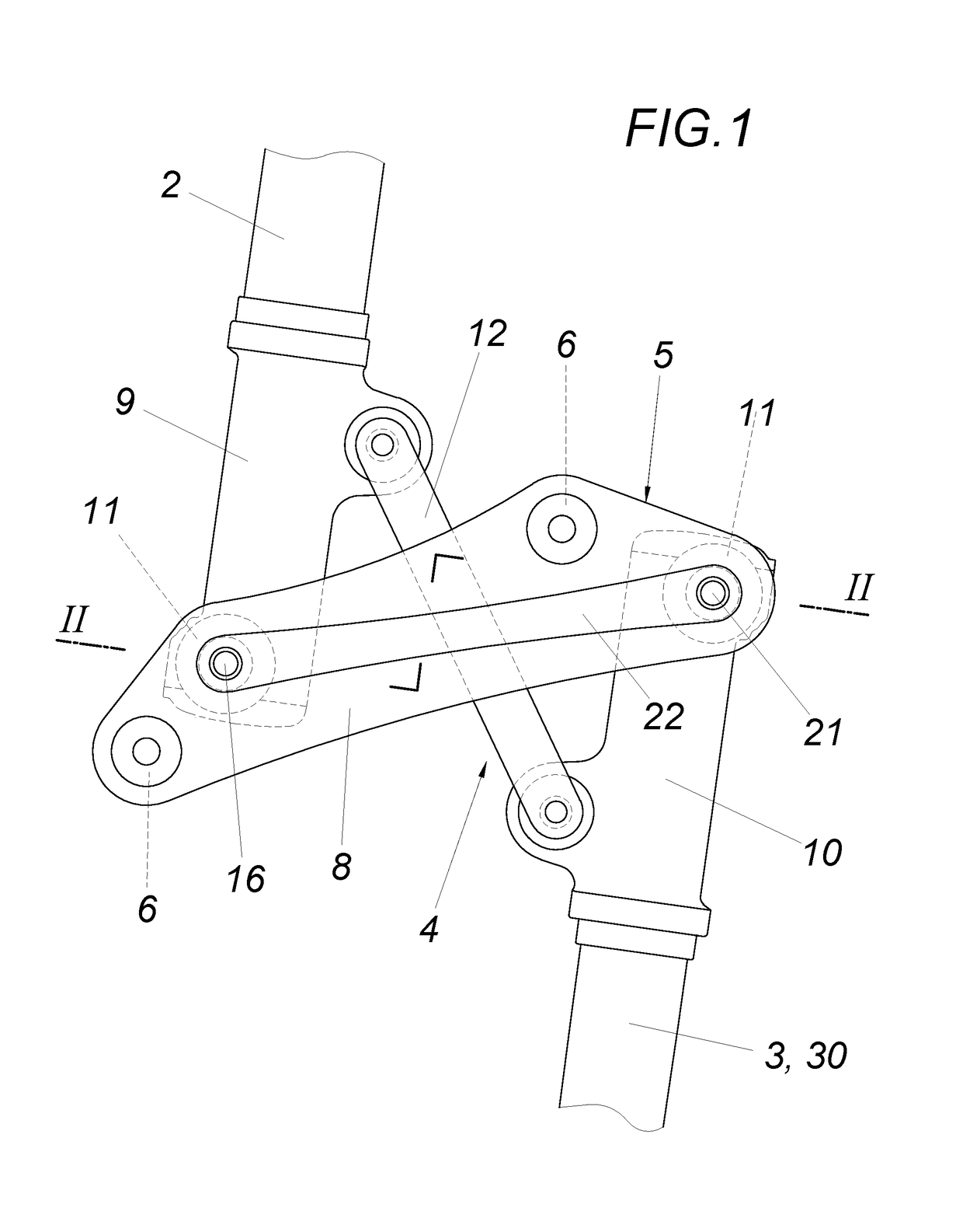
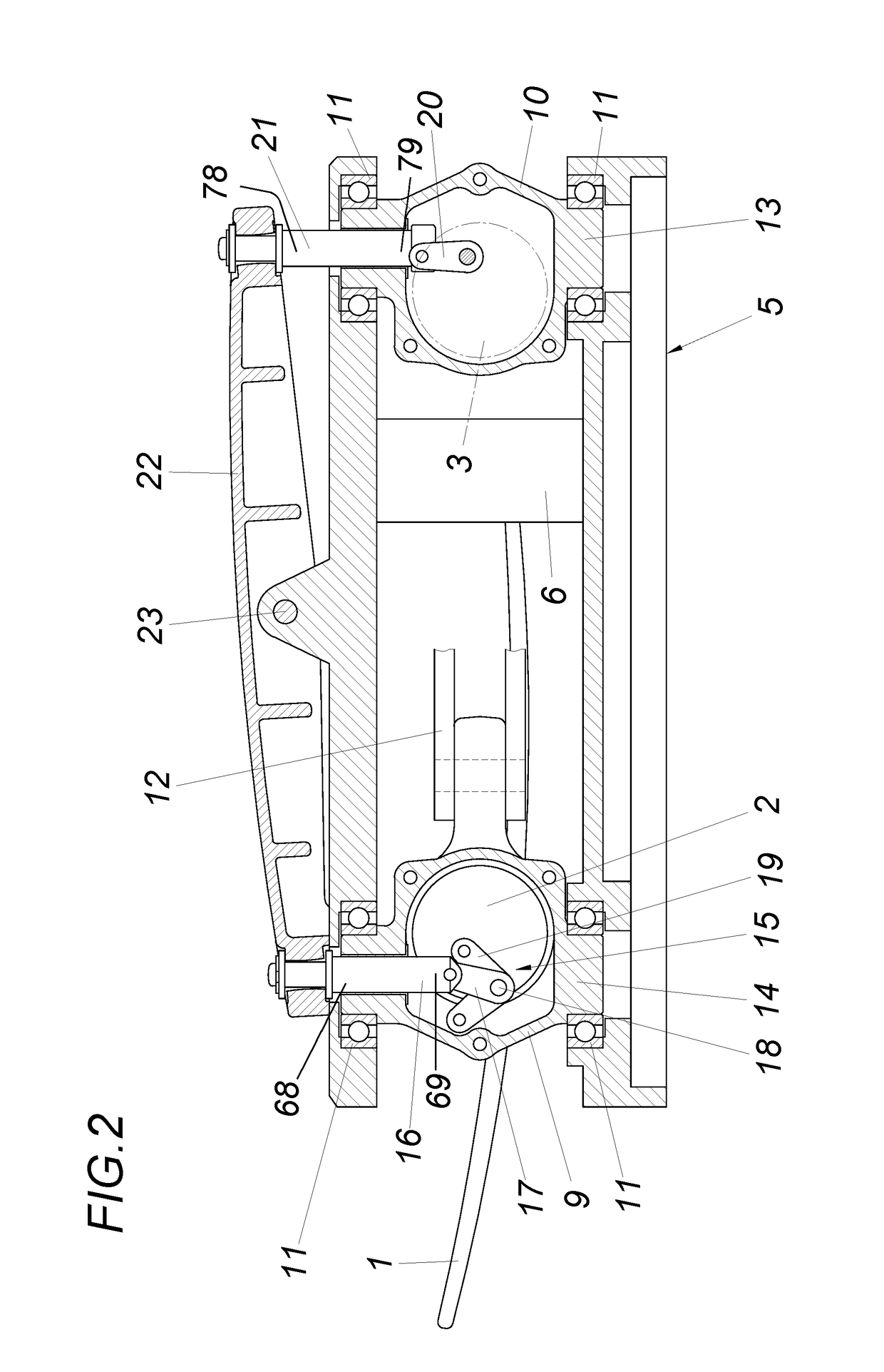
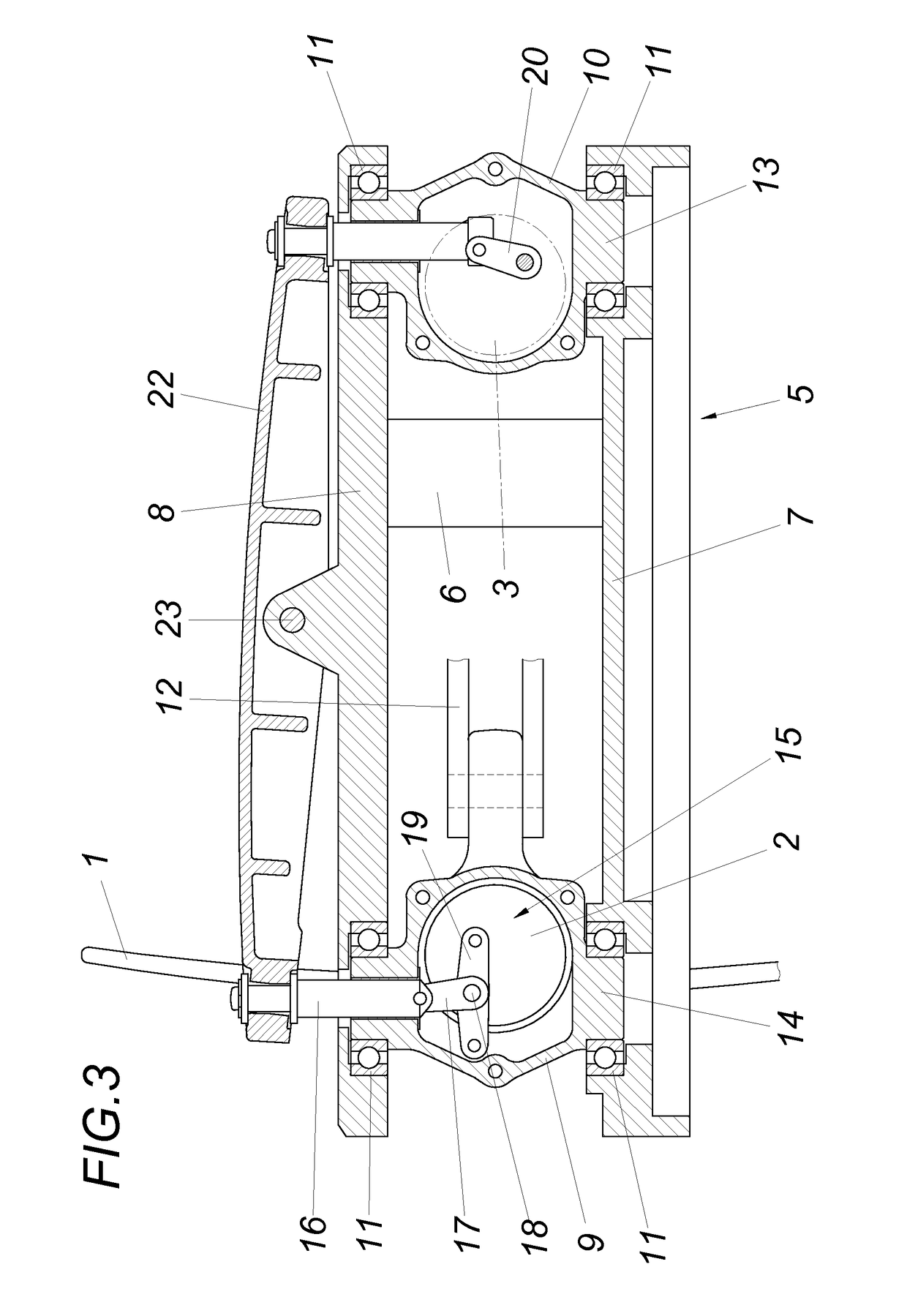
[0018]The apparatus to row in the direction the rower is facing requires an oar blade (1) mounted on an oar lever (2) with a separate grip lever (3) that is linked to the oar lever (2) by a reversing unit in the form of a counteracting four-bar linkage system (4), as shown in particular in FIG. 1. This four-bar linkage system (4) consists of a base frame (5) with two plates (7, 8) held apart by spacers (6) in which the first and second bearing bodies (9, 10) are mounted on axle bearings. The oar lever (2) is mounted on the first bearing body (9) and is free to rotate about its axis. In the same way, the grip lever (3) is mounted on the second bearing body (10). The second bearing body (10) forms the driving crank of the four-bar linkage system together with the first bearing body (9) and the linkage (12). If the second bearing body (10) is pivoted by the grip lever (3) about its bearing axle (13) mounted in bearings (11), the first bearing body (9) with the oar lever (2) is pivoted ...


PUM


Abstract

Apparatus for rowing in the direction the rower is facing has a base frame. A main bearing for a lever with hand grip and another for a lever with oar are in the base frame. A linkage connects the lever with hand grip and lever with oar to form a counteracting four-bar linkage system. The oar lever is the driven arm of the four-bar linkage and is linked to a rotary drive that has a main axle and virtually coaxial actuator rod. The hand grip lever rotates about its axis and is mounted to a bearing body within the base frame. The hand grip lever actuates an actuator that is virtually coaxial to the main axle on the bearing body. The actuator engages with a seesaw mounted on the base frame to shift the actuator rod of the rotary drive to rotate the oar.

Description

CROSS REFERENCE TO RELATED APPLICATIONS[0001]Applicant claims priority under 35 U.S.C. § 119 of Austrian Application No. A50607 / 2014 filed Sep. 3, 2014, the disclosure of which is incorporated by reference.BACKGROUND OF THE INVENTION1. Field of the Invention[0002]The invention is for an apparatus for rowing in the direction the rower is facing with a base frame, where the main bearing for a lever with a hand grip, i.e. a grip lever, and for a lever with an oar, i.e. an oar lever, and a linkage that connects the grip lever and the oar lever to form a counteracting four-bar linkage system with actuated bearing body as the driven arm of the four-bar linkage and linked to a rotary drive with a main axle and virtually coaxial actuator2. Description of the Prior Art[0003]To row in the direction the rower is facing, an oar lever with the oar blade is implemented separately from the grip lever in a way that the oar lever makes the opposite movement so that when the rower makes a recovery st...

Claims


Application Information

Patent Timeline
Patent Type & Authority Patents(United States)
IPC IPC(8): B63H16/00B63H16/10
CPCB63H16/105B63H16/10B63B34/30
Inventor BIERMA, JOCHUM
Owner BIERMA JOCHUM
Why Eureka
Try Eureka