
Dynamic multi-sensor and multi-robot interface system

a multi-sensor and multi-robot technology, applied in the field of adaptive learning interface systems, can solve the problems of complex problem, complicated problem, and high cost of setup effor

Active Publication Date: 2019-01-15
ROBOLOGICS LTD
View PDF27 Cites 2 Cited by
  • Summary
  • Abstract
  • Description
  • Claims
  • Application Information

AI Technical Summary

Benefits of technology

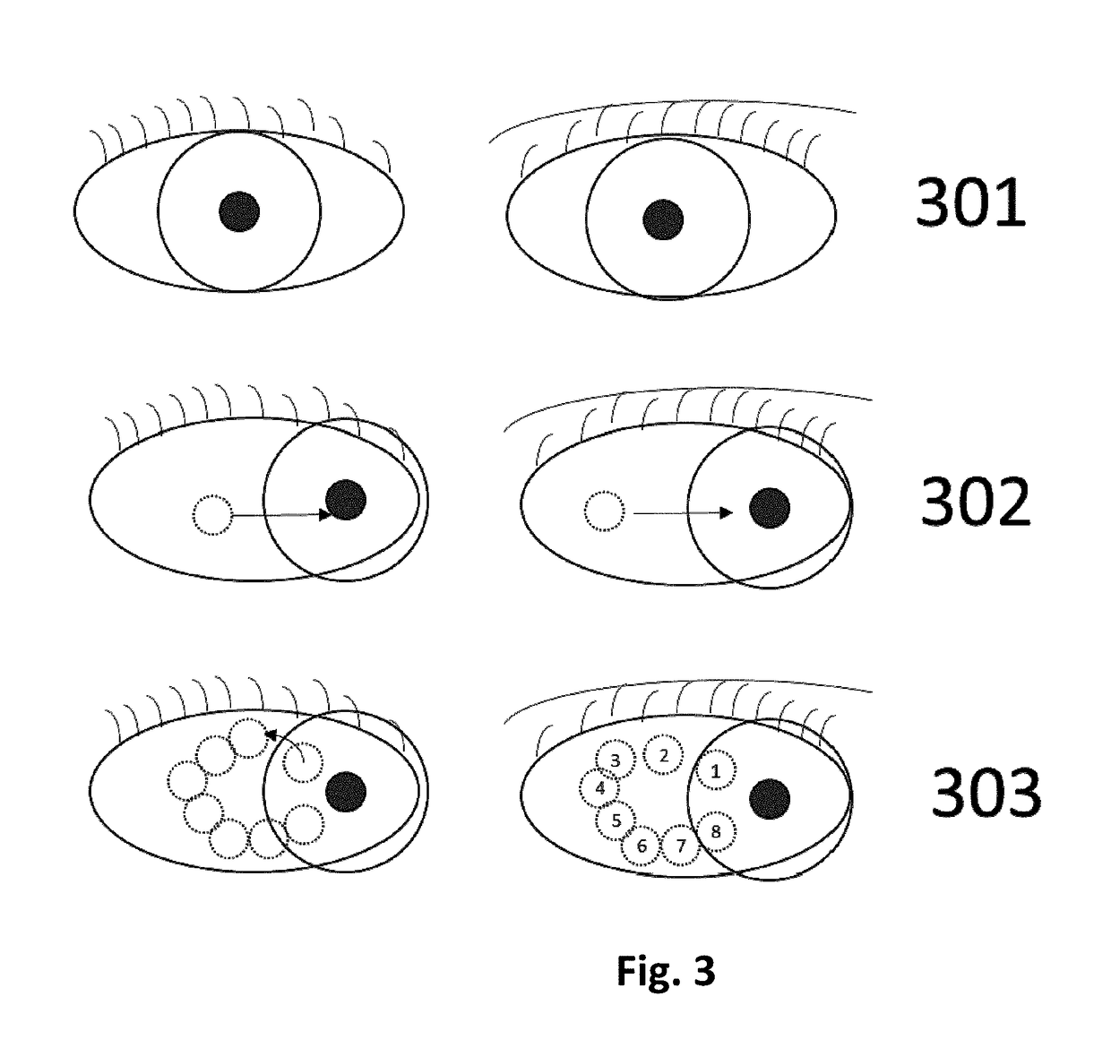
[0027]Optionally, this scalar factor can be edited by the end-user, enabling him to change the distance that the robot will be displaced in space for each pixel displacement on a gaze detection track. This acts as a sort of virtual gear for the robot being controlled, where step movements can be increased or decreased by a scale factor.

Problems solved by technology

When multiple sensors and robots are combined, obtaining these equivalent coordinates becomes very complex.
In a less static environment, an initial setup effort to estimate these relative positions is not enough as both robots' bases and sensors might change positions in an untraceable way, and therefore the relative positions between them will not always be the same.
While requiring setup effort, there are many methods to translate coordinates between devices in the static scenario described above.
For a dynamically changing scenario, where sensors and robots change their relative position with regards to each other, the problem is more complicated and there are no practical and dynamical methods available that solve this in a simple and timely manner.

Method used


Image

  • Dynamic multi-sensor and multi-robot interface system
  • Dynamic multi-sensor and multi-robot interface system
  • Dynamic multi-sensor and multi-robot interface system

Examples


Embodiment Construction

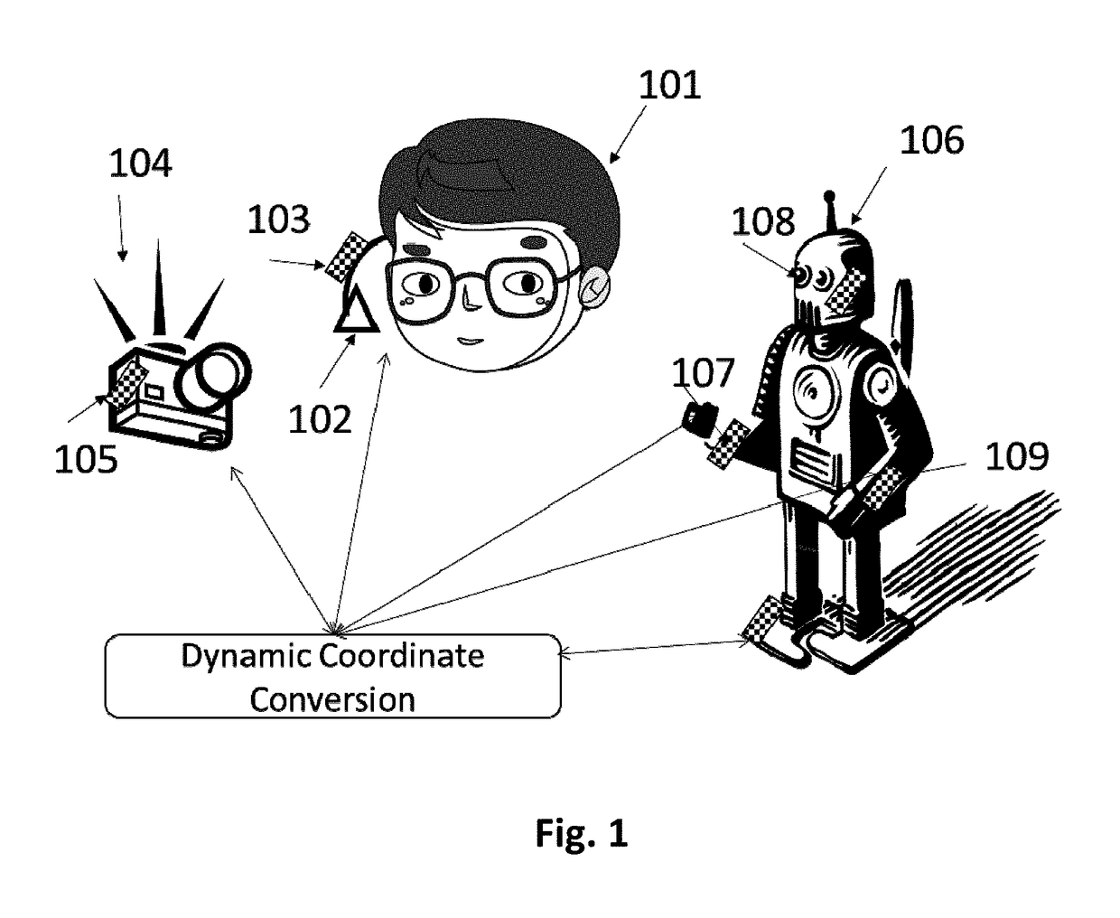
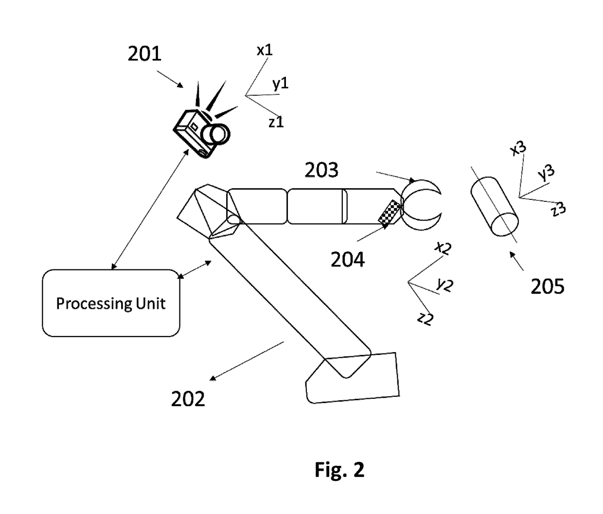
[0053]According to some embodiments of the present invention, there is provided a method for defining a common coordinate system between robots and sensors in a given environment. The method comprises collecting a sequence of a plurality of images showing at least one sensor and / or one mechanical device with internal coordinate system, such as a robotic arm, performing an analysis of the sequence of a plurality of images to identify the sensor or machine in the scene and to determine its relative position with regards to the sensor from where the sequence of images was collected, creating a dynamic function and parameters required to transform any given coordinates from / to the generating sensor to / from the detected sensor or machine.

[0054]Optionally, the plurality of images are complemented by corresponding depth maps or other special correlating matrices. The analysis includes object recognition algorithms to detect the rest of the sensors and / or robots in the environment.

[0055]Opt...


PUM


Abstract

An adaptive learning interface system for end-users for controlling one or more machines or robots to perform a given task, combining identification of gaze patterns, EEG channel's signal patterns, voice commands and / or touch commands. The output streams of these sensors are analyzed by the processing unit in order to detect one or more patterns that are translated into one or more commands to the robot, to the processing unit or to other devices. A pattern learning mechanism is implemented by keeping immediate history of outputs collected from those sensors, analyzing their individual behavior and analyzing time correlation between patterns recognized from each of the sensors. Prediction of patterns or combination of patterns is enabled by analyzing partial history of sensors' outputs. A method for defining a common coordinate system between robots and sensors in a given environment, and therefore dynamically calibrating these sensors and devices, is used to share characteristics and positions of each object detected on the scene.

Description

CROSS REFERENCE[0001]This application claims the benefit of U.S. Provisional Patent Application No. 62 / 080,353 filed on Nov. 16, 2014 and entitled Dynamic Multi-Sensor and Multi-Robot Learning Interface System.TECHNICAL FIELD[0002]The present invention pertains to adaptive learning interface system for controlling and operating robotic devices. More particularly the present invention pertains to such controlling and operating of robotic devices with human produced signals.FIELD AND BACKGROUND OF THE INVENTION[0003]The present invention, in some embodiments thereof, relates to a dynamic multi-sensor and multi-machine calibration method.[0004]Computer and robotic applications that include some level of interaction with the physical environment, require estimating and sharing the 2D or 3D coordinates of objects detected in the given environment. When more than one sensor or actuator is involved, it's critical to have these coordinates translated to a relative position with respect to t...

Claims


Application Information

Patent Timeline
Patent Type & Authority Patents(United States)
IPC IPC(8): B25J9/16B25J13/00G06F3/01G06F3/0484
CPCB25J9/1692B25J13/00G06F3/011G06F3/013G06F3/0484G06F3/015Y10S901/16B25J9/1697G05B2219/35503Y10S901/09
Inventor BENAIM, CARLOS
Owner ROBOLOGICS LTD
Learn More