Steering column apparatus

a technology of steering column and assembly efficiency, which is applied in the direction of steering column, steering parts, vehicle components, etc., can solve the problems affecting the stability of energy absorption, so as to achieve stable energy absorption and unstable energy absorption performance. , the effect of lowering the assembly efficiency of the steering column apparatus

Inactive Publication Date: 2019-01-22
FUJI KIKO CO LTD
View PDF25 Cites 2 Cited by
  • Summary
  • Abstract
  • Description
  • Claims
  • Application Information

AI Technical Summary

Benefits of technology

[0006]In the steering column apparatus of US Patent Application Publication No. 2009 / 0218801, a load itself necessary for drawing the wire from the hole is relatively large. With this, the energy absorbing performance may be unstable. Furthermore, it is necessary to attach the wires for the energy absorption at the same time when inserting the tilt jacket and the upper jacket. This may lower the assembly efficiency of the steering column apparatus.

Problems solved by technology

With this, the energy absorbing performance may be unstable.
This may lower the assembly efficiency of the steering column apparatus.
This may interfere with the straight movement of the column, thereby damaging a stable energy absorption.

Method used


Image

  • Steering column apparatus
  • Steering column apparatus
  • Steering column apparatus

Examples


first embodiment

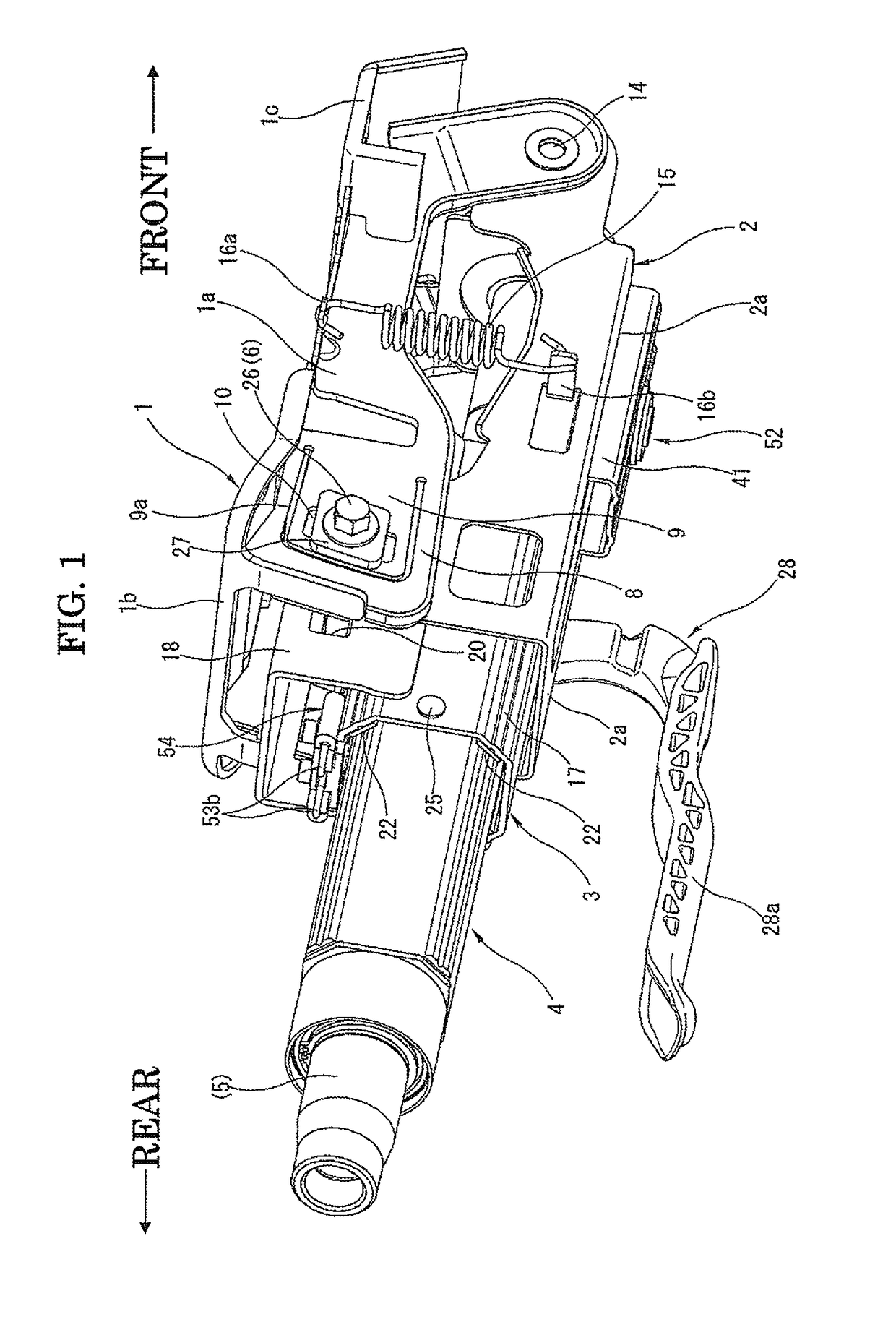
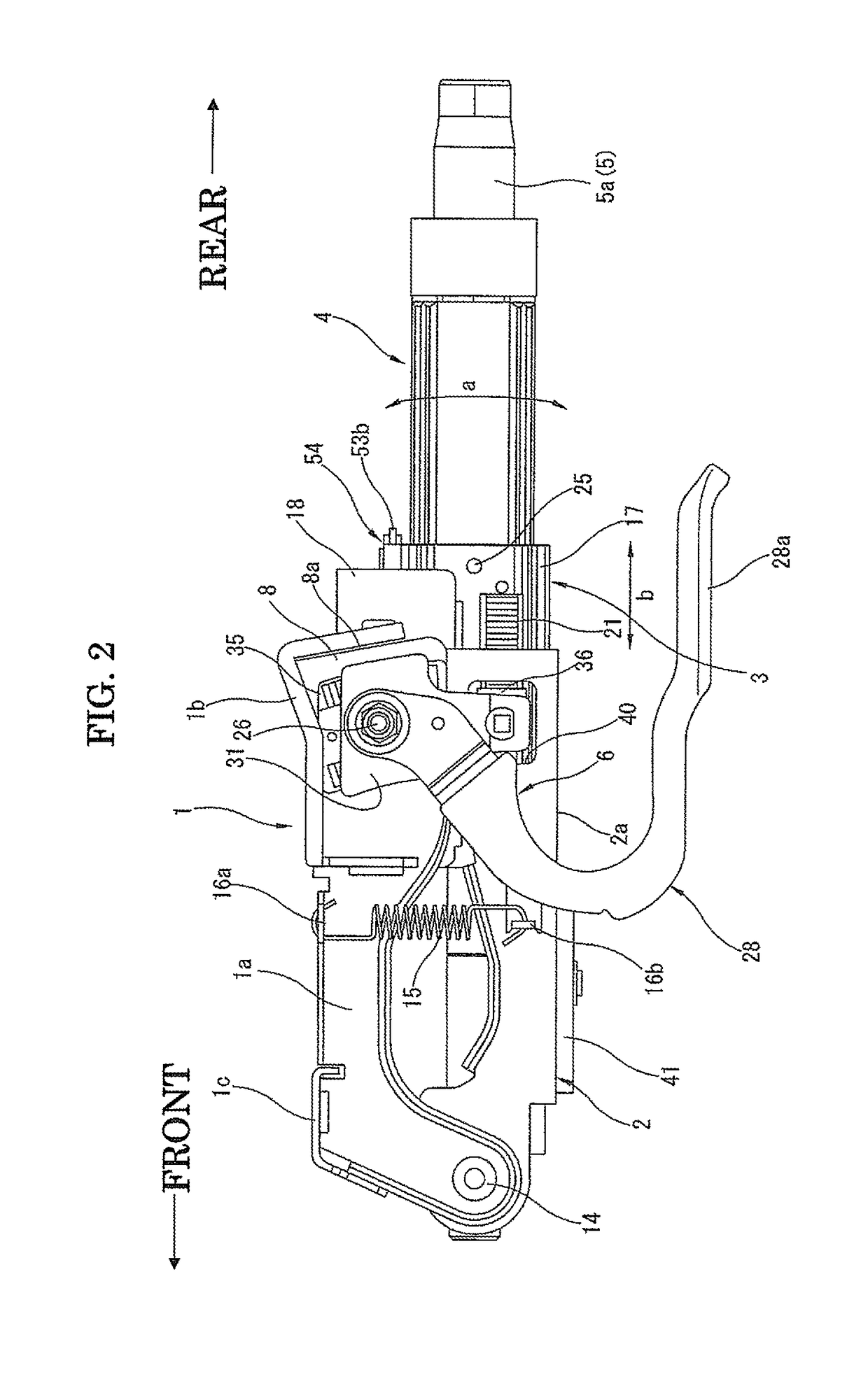
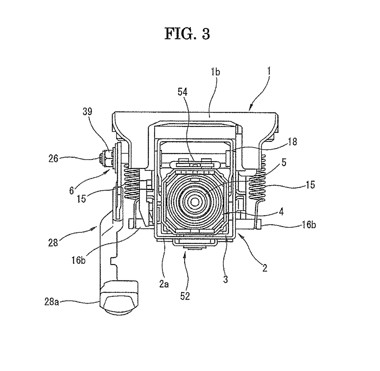
[0049]With reference to FIGS. 1 to 10B, a steering column apparatus according to the present invention, which corresponds to the above-mentioned first to fourth steering column apparatuses, is explained in detail as follows. This steering column apparatus is capable of conducting a tilt operation of the steering wheel in upward and downward directions and a telescopic operation of the steering wheel in forward and rearward directions. These directions and others are defined with reference to the steering column apparatus installed in a motor vehicle. For example, the forward direction refers to the front side of the motor vehicle.

[0050]As shown in FIGS. 1 and 2, the steering column apparatus is mainly equipped with (a) a vehicle body attachment bracket 1 (hereinafter simply referred to as “attachment bracket”) that serves as a member for attachment to a vehicle body (not shown in the drawings), (b) a tilt bracket (lower bracket) 2 that is supported by the attachment bracket 1 to be ...

second embodiment

[0125]The tilt position adjustment operation and the telescopic position adjustment operation in the steering column apparatus having the above structure according to the present invention are explained in the following.

[0126]As shown in FIG. 11, it is a locked condition in which the operation lever 121 extends to be generally parallel with the steering column. In this condition, the movable cam member 122 and the fixed cam member 123 ride on each other at their raised portions. With this, both of the tilt position adjustment function and the telescopic position adjustment function of the steering column or steering wheel are in a locked condition.

[0127]That is, in the locked condition, the raised portions of the movable cam member 122 and the fixed cam member 123 ride on each other. With this, the operation shaft 120 is pulled in a relative manner in its axial direction toward its head side, thereby narrowing the distance between the fixed cam member 123 and the receiving piece 124...


PUM


Abstract

Disclosed is a steering column apparatus including an impact energy absorbing mechanism for absorbing an impact energy at a secondary collision. The impact energy absorbing mechanism includes an energy absorbing section that serves as a load generating section for absorbing the impact energy. The energy absorbing section includes (a) a resistive member that extends along an axial direction of the middle jacket and is fixed to the middle jacket and (b) a wire having a bent portion that is wound around the resistive member to have a curvature and a front portion that is fixed to the upper jacket, the front portion being at a more forward position than the bent portion.

Description

BACKGROUND OF THE INVENTION[0001]The present invention relates to a steering column apparatus to be installed in a motor vehicle and particularly to a steering column apparatus equipped with a tilt position adjusting function for adjusting the position of the steering wheel and an impact energy absorbing mechanism at a secondary collision by the driver against the steering wheel.[0002]US Patent Application Publication No. 2009 / 0218801 discloses such a steering column apparatus equipped with a tilt position adjusting function for adjusting the position of the steering wheel in the upward and downward directions and an impact energy absorbing mechanism at a secondary collision by the driver against the steering wheel.[0003]This steering column apparatus is equipped with (a) a tilt jacket that is fixed to a vehicle attachment bracket through a tilt shaft to be adjustable in the upward and downward directions, (b) an upper jacket fixed to the tilt jacket to be compressible in the axial ...

Claims


Application Information

Patent Timeline
Patent Type & Authority Patents(United States)
IPC IPC(8): B62D1/19B62D1/187
CPCB62D1/187B62D1/195B62D1/192
Inventor MATSUNO, MITSUYOSHISAWAMURA, KOJITANAKA, SOITO, TADAOSHIMADA, AYASAKAMOTO, MASATOSHIKATAKURA, REO
Owner FUJI KIKO CO LTD
Why Eureka
Try Eureka