Electronic device with heat dissipation unit

Inactive Publication Date: 2013-01-10
HONG FU JIN PRECISION IND (SHENZHEN) CO LTD +1
View PDF8 Cites 1 Cited by
  • Summary
  • Abstract
  • Description
  • Claims
  • Application Information

AI Technical Summary

Benefits of technology

The invention provides a heat dissipation unit for electronic devices, which includes a heat sink and a fan with a power cord. However, there is a technical problem of aligning the electrical connector with the power connector when connecting them, which can make assembly of the device more difficult and inefficient. The invention aims to solve this problem to improve assembly efficiency of electronic devices.

Problems solved by technology

This may be difficult and inconvenient if the electrical connector and the power connector are both small, and further reduce the assembly efficiency of the electronic device.

Method used


Image

  • Electronic device with heat dissipation unit
  • Electronic device with heat dissipation unit
  • Electronic device with heat dissipation unit

Examples


Embodiment Construction

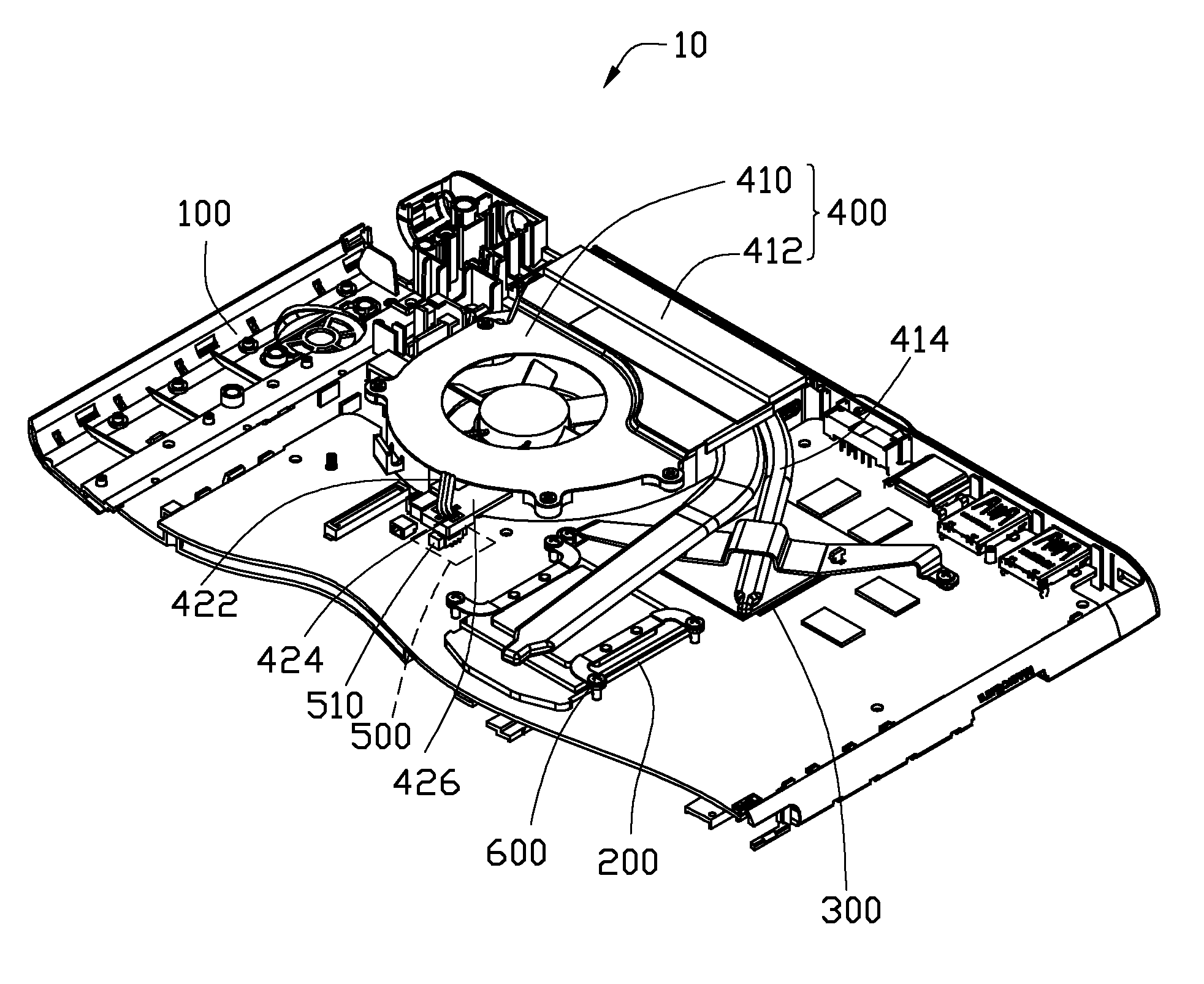
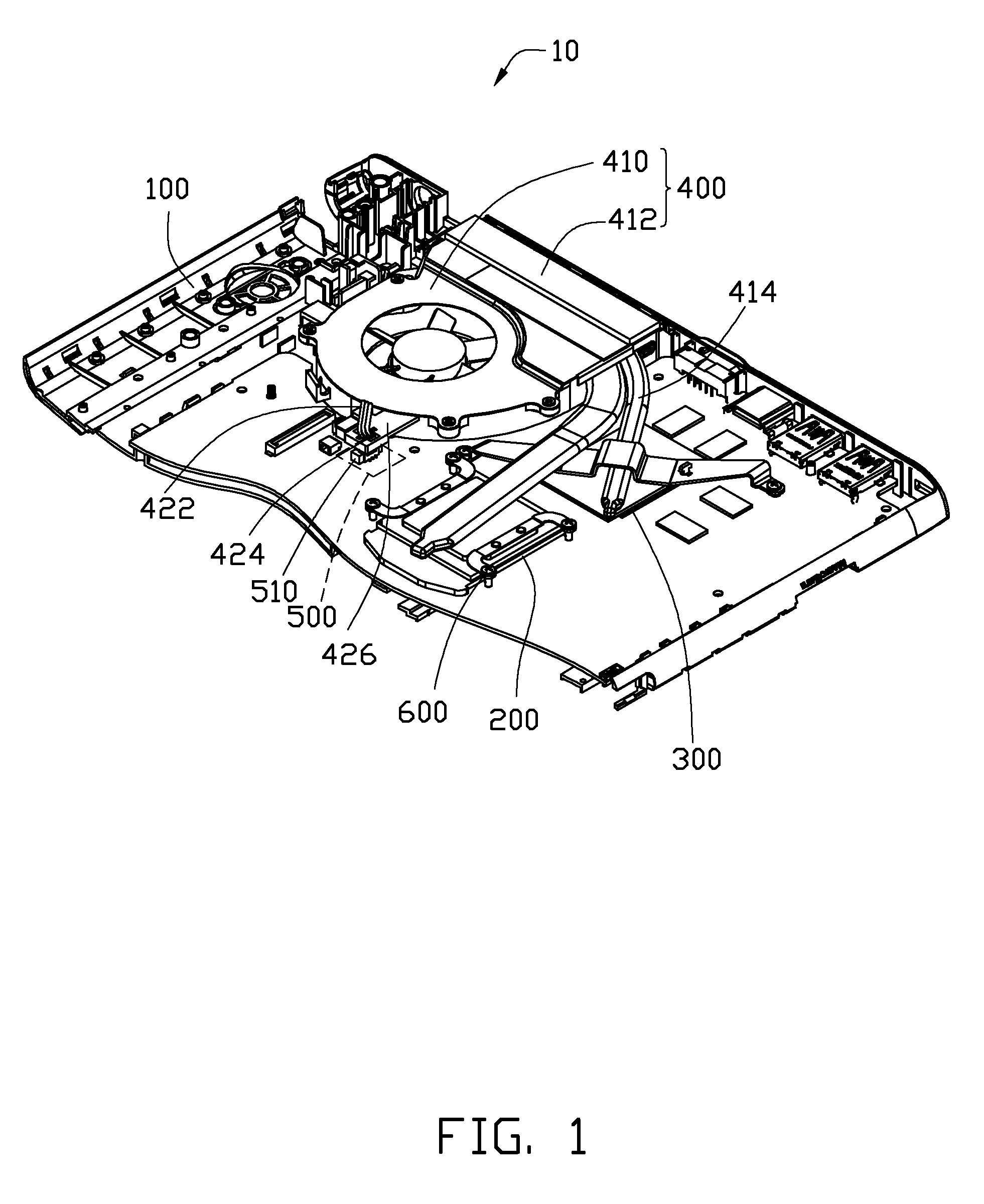
[0012]Referring to FIG. 1, an electronic device 10 includes a housing 100, a heat dissipation unit 400, and a power supply unit 500 with a power connector 510. The heat dissipation unit 400 is thermally connected to heat sources of the electronic device 10, for example, a central processing unit (CPU) 200 and a display card 300 of the electronic device 10, for absorbing and removing heat produced by the heat sources. The heat dissipation unit 400 is also connected to the power supply unit 500 by the power connector 510. In some embodiments, the electronic device 10 is a notebook computer. In other embodiments, the electronic device 10 may be other devices with a heat dissipation unit, and the heat sources may be other components of the electronic device 10.

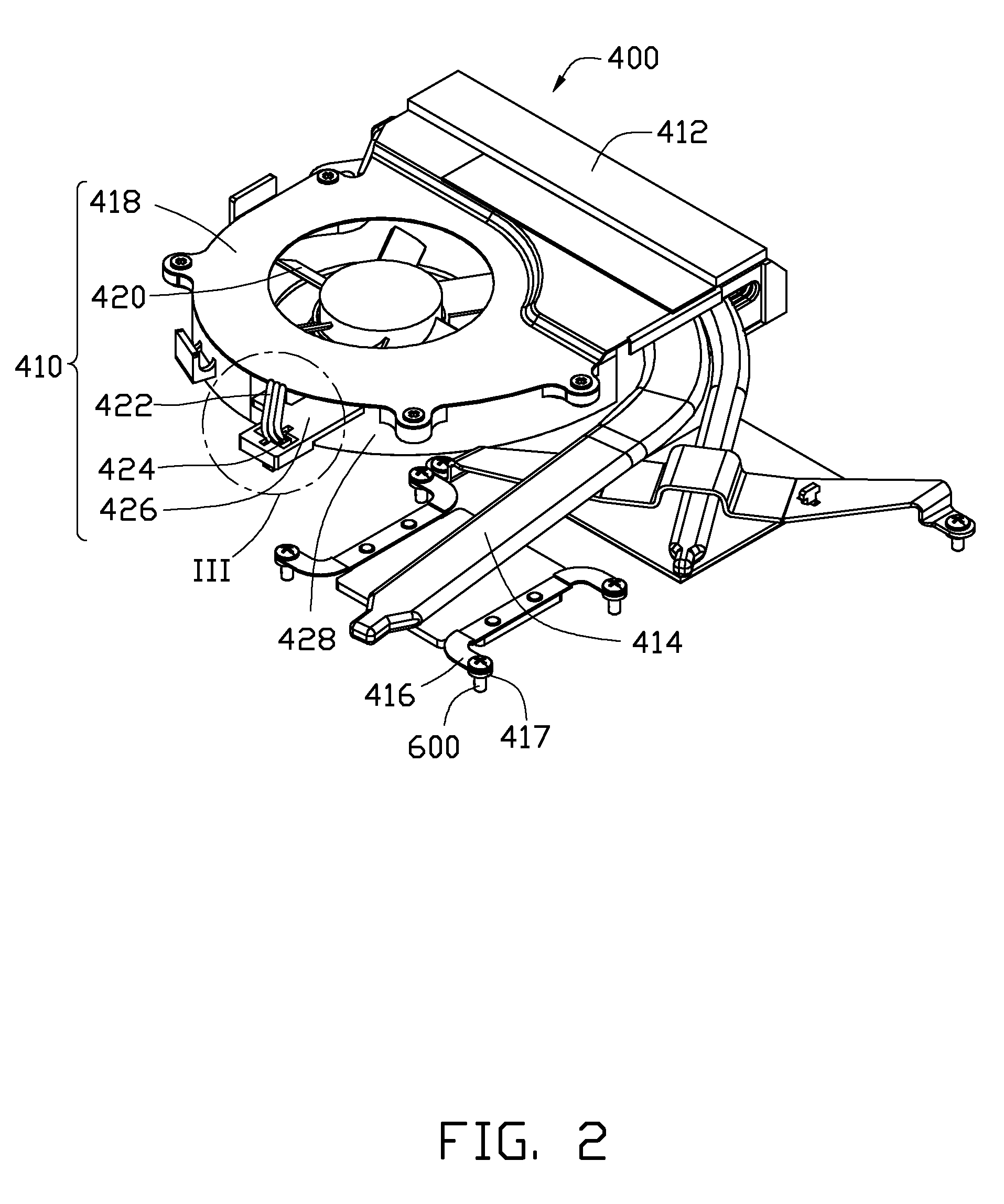
[0013]Referring also to FIGS. 2 and 3, the heat dissipation unit 400 includes a fan 410, a heat sink 412, and a number of fixing members 416. The heat sink 412 includes two heat pipes 414 and a number of fins (not shown). The heat...


PUM


Abstract

A heat dissipation unit for radiating heat produced by at least one heat source of an electronic device includes a fan, at least an electrical connector, and a latching member. The fan has at least one power cord. The at least one connector is connected to the at least one power cord and is engageable with a power connector of a power supply unit of the electronic device. The latching member corresponds to the power connector for clasping the electrical connector therein. The electrical connector is clasped in the latching member for being aligned with the power connector of the electronic device.

Description

BACKGROUND[0001]1. Technical Field[0002]The present disclosure relates to electronic devices, and in particular, to an electronic device with a heat dissipation unit.[0003]2. Description of Related Art[0004]A heat dissipation unit is often disposed in an electronic device such as a notebook computer for radiating heat. The heat dissipation unit often includes a heat sink and a fan with a power cord adjacent to the heat sink. In assembly, the power cord is connected to an electrical connector which is plugged into a power connector of a power supply unit such that the power supply unit can supply power to the fan. When plugging the electrical connector into the power connector, the electrical connector should be aligned with the power connector. This may be difficult and inconvenient if the electrical connector and the power connector are both small, and further reduce the assembly efficiency of the electronic device.[0005]Therefore, there is room for improvement in the art.BRIEF DES...

Claims


Application Information

Patent Timeline
IPC IPC(8): H05K7/20
CPCG06F1/203H01R13/743H05K7/20172
Inventor LIN, JU-SHANSUNG, TE-JENLUO, GUANG-LIANG
Owner HONG FU JIN PRECISION IND (SHENZHEN) CO LTD
Why Eureka
Try Eureka