
Spark plug

a technology of spark plugs and plugs, which is applied in the direction of spark plugs, sparking plugs, basic electric elements, etc., can solve the problems of not having sufficient studies on how to dissipate heat sufficiently, ignition to occur before spark discharge, etc., and achieve the effect of improving heat dissipation through the path from the insulator through the sheet packing to the metallic shell, sufficient deformation allowance, and improving heat dissipation through the path

Active Publication Date: 2019-01-22
NGK SPARK PLUG CO LTD
View PDF17 Cites 1 Cited by
  • Summary
  • Abstract
  • Description
  • Claims
  • Application Information

AI Technical Summary

Benefits of technology

The patent text describes a new invention that can be used in various forms, such as a component of a spark plug or a method of producing the spark plug. The technical effect of this invention is to improve the performance and efficiency of the spark plug in engines.

Problems solved by technology

When the temperature of the center electrode of the spark plug is excessively high (e.g., 950° C. or higher), pre-ignition occurs in which the center electrode serves as a heat source and causes ignition to occur before spark discharge is generated.
In the spark plug in WO 2011 / 125306, there are no sufficient studies on how to dissipate heat sufficiently through a path extending from the insulator through the sheet packing to the metallic shell.

Method used


Image

  • Spark plug
  • Spark plug
  • Spark plug

Examples


first embodiment

A. First embodiment

A-1. Configuration of Spark Plug

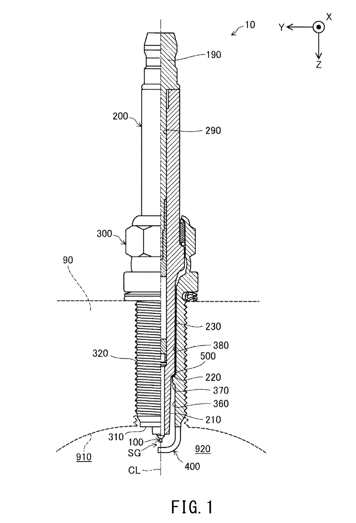
[0028]FIG. 1 is an illustration showing a partial cross section of a spark plug 10. In FIG. 1, the exterior shape of the spark plug 10 is shown on the left side of the sheet with respect to an axial line CL, i.e., the axis of the spark plug 10, and a cross-sectional shape of the spark plug 10 is shown on the right side of the sheet with respect to the axial line CL. In the description of the present embodiment, the lower side in the sheet of FIG. 1 is referred to as a “forward end side” of the spark plug 10, and the upper side in the sheet of FIG. 1 is referred to as a “rear end side.”

[0029]The spark plug 10 includes a center electrode 100, an insulator 200, a metallic shell 300, a ground electrode 400, and a sheet packing 500. In the present embodiment, the axial line CL of the spark plug 10 is also the axis of the center electrode 100, the axis of the insulator 200, and the axis of the metallic shell 300.

[0030]The spark plug 10 ha...


PUM


Abstract

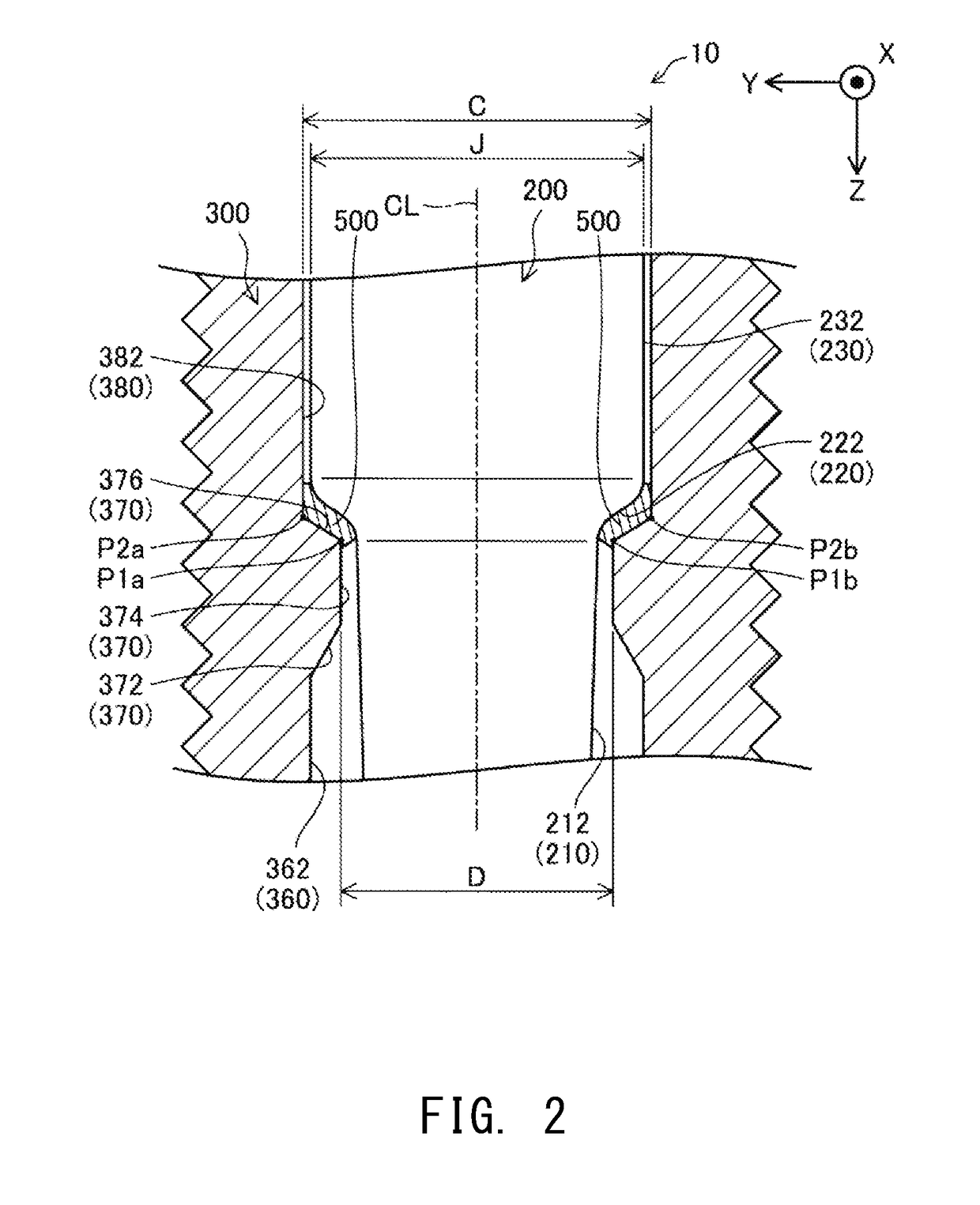
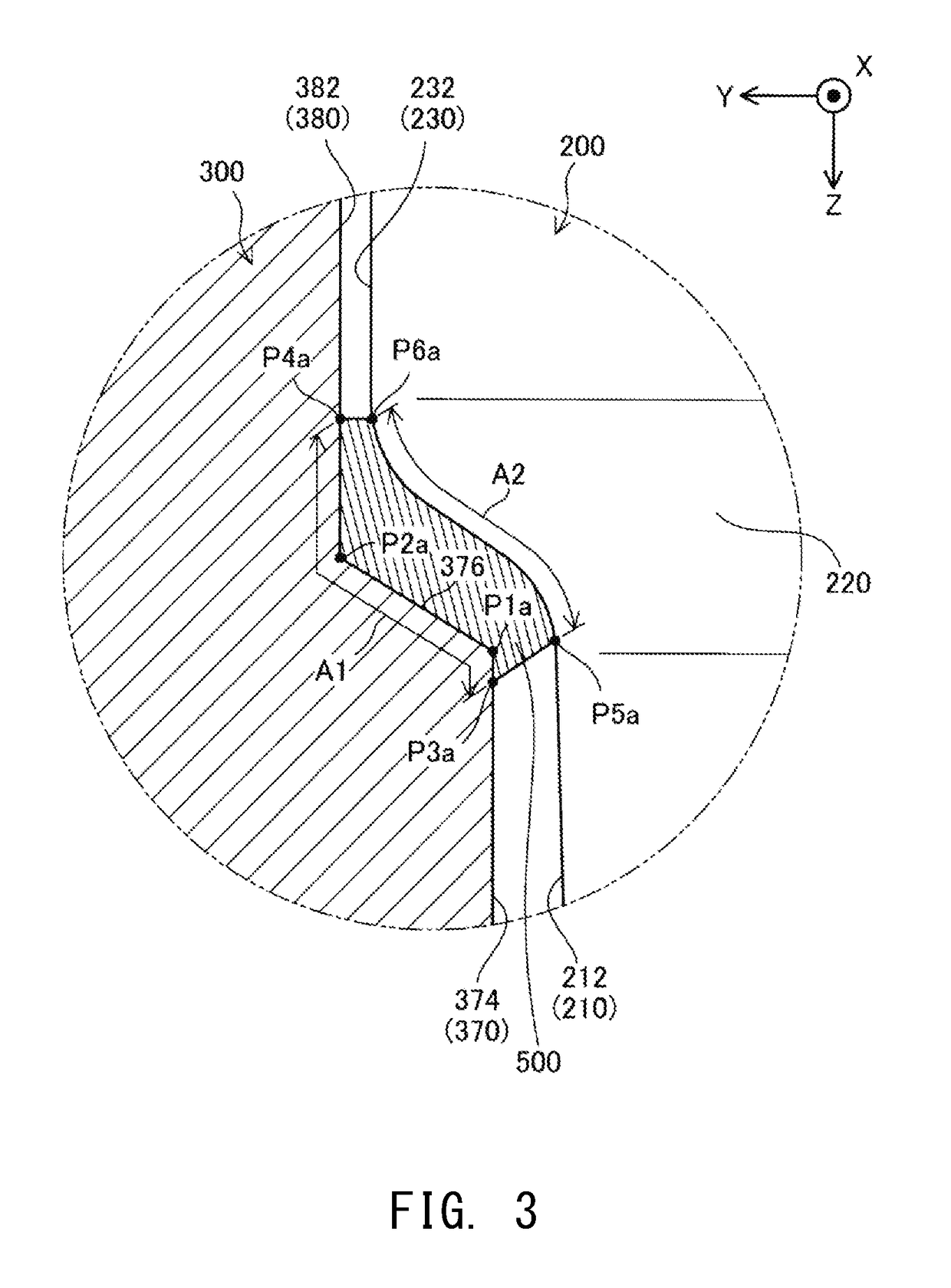
A spark plug that satisfies the relation 2.8≤(A+B) / M, where A is the sum of a length A1 of contact between a sheet packing and a metallic shell of a spark plug in one half section and a length A2 of contact between the sheet packing and the insulator in the one half section, and B is the sum of a length B1 of contact between the sheet packing and the metallic shell in the other half section and a length B2 of contact between the sheet packing and the insulator in the other half section. M is the difference obtained by subtracting the inner diameter D of a ledge from the inner diameter C of a middle hole portion.

Description

RELATED APPLICATIONS[0001]This application is a National Stage of International Application No. PCT / JP15 / 01115filed Mar. 3, 2015, which claims the benefit of Japanese Patent Application No. 2014-079844, filed Apr. 9, 2014.FIELD OF THE INVENTION[0002]The present invention relates to a spark plug.BACKGROUND OF THE INVENTION[0003]One known spark plug includes an insulator that internally holds a center electrode and a metallic shell that internally holds the insulator. In such a spark plug, a sheet packing is held between the insulator and the metallic shell in order to ensure air tightness therebetween (see, for example, WO 2011 / 125306).[0004]When the temperature of the center electrode of the spark plug is excessively high (e.g., 950° C. or higher), pre-ignition occurs in which the center electrode serves as a heat source and causes ignition to occur before spark discharge is generated. In a spark plug, its heat range (heat dissipation properties), which is the degree of dissipation ...

Claims


Application Information

Patent Timeline
Patent Type & Authority Patents(United States)
IPC IPC(8): H01T13/20H01T13/36H01T13/00H01T13/16
CPCH01T13/16H01T13/36H01T13/20H01T13/00H01T13/05
Inventor KOBAYASHI, TSUTOMUIGARASHI, TOMOYUKI
Owner NGK SPARK PLUG CO LTD
Learn More