Torque sensing in a surgical robotic wrist

a robotic wrist and torque sensing technology, applied in the field of robots, can solve the problems of insufficient space, inability to locate the robot base, and excessive weight of the robot,

Active Publication Date: 2019-02-19
CMR SURGICAL LTD
View PDF26 Cites 184 Cited by
  • Summary
  • Abstract
  • Description
  • Claims
  • Application Information

AI Technical Summary

Problems solved by technology

However, many robot designs suffer from problems that make them unsuitable for performing a wide range of surgical procedures.
However, secondly, a surgical robot must also be capable of positioning its arm such that the end effector of the instrument is positioned very accurately without the robot being excessively large or heavy.
Another problem with the robot of FIG. 1 is that in some surgical environments there is not sufficient space to be able to locate the base of the robot in a convenient location near the operating site.
However, this wrist is not well suited for use in a surgical robot.
This requirement is not readily compatible with making the arm small and lightweight because it calls for a relatively large drive motor and a sufficiently stiff arm that the motor can react against it without jolting the position of the arm.
Because the surgeon is not directly in contact with the surgical instrument during robotic surgery, tactile feedback is lost compared to manual surgery.
This lack of tactile sensation means that the surgeon does not know how much force is being applied when using the surgical instrument.
This affects the surgeon's dexterity.
Additionally, too much exerted force can cause internal damage to the patient at the surgical site, and can also damage the surgical instrument and the robot arm.
However, forces which are applied to the surgical instrument from other directions cannot be sensed using torque sensors applied to the wrist.
However, these other techniques require more sensors to be applied to the robot, and hence more electronics are required to route and process the data, which increases the weight and power requirements of the robot.

Method used


Image

  • Torque sensing in a surgical robotic wrist
  • Torque sensing in a surgical robotic wrist
  • Torque sensing in a surgical robotic wrist

Examples


Embodiment Construction

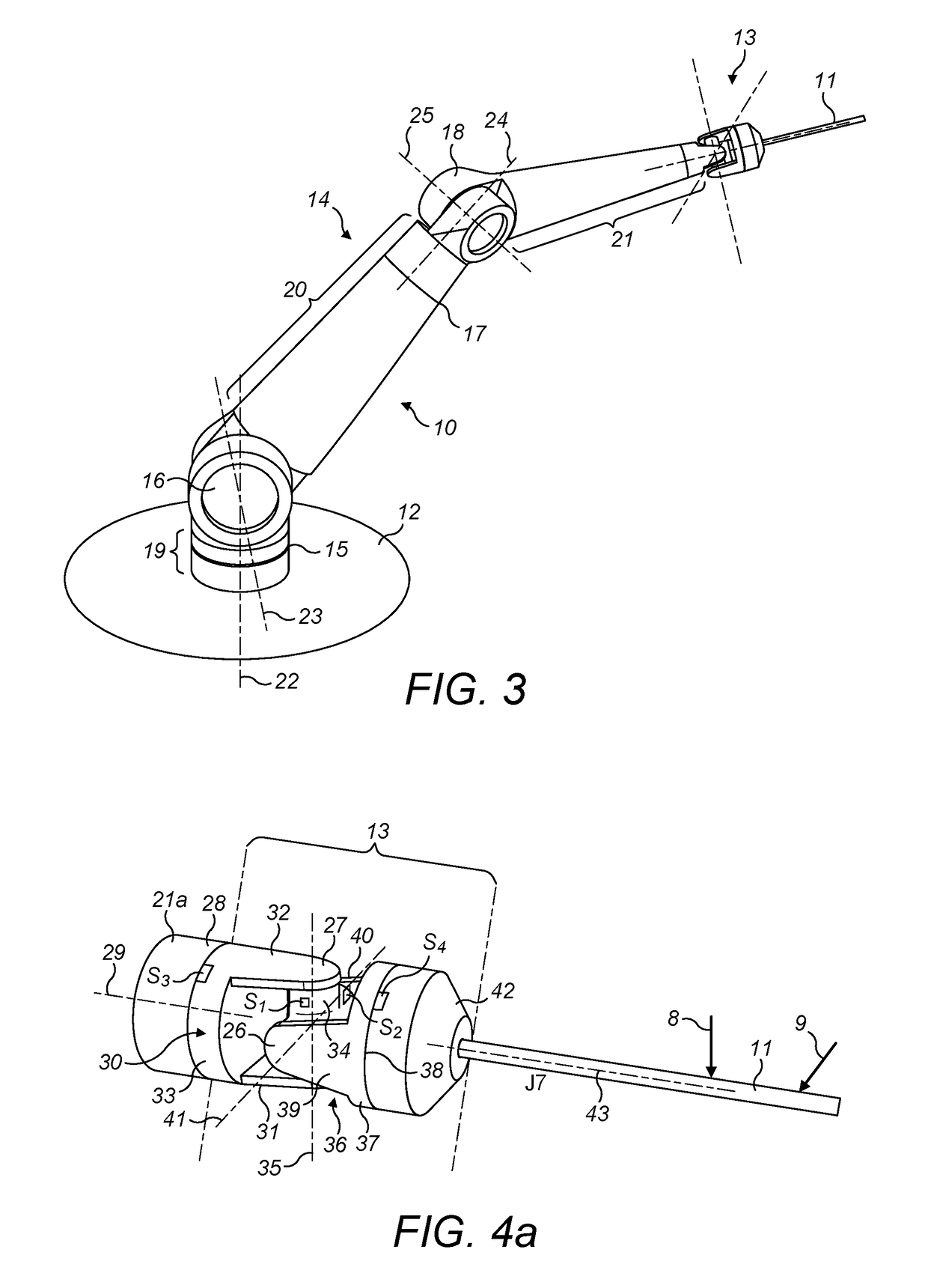
[0026]The surgical robot arm of FIG. 3 has a wrist in which two joints that permit rotation about axes generally transverse to the distal portion of the arm are located between two joints that permit rotation about axes generally parallel to the distal portion of the arm. This arrangement permits the instrument to move in a hemispherical space whose base is centred on the distal part of the arm, but without requiring high-speed motion of one of the joints in order to move the end effector smoothly, and without requiring motion of any of the other parts of the arm.

[0027]In more detail, FIG. 3 shows a robot arm (indicated generally at 10) having a surgical instrument 11 attached thereto. The robot arm extends from a base 12. The base could be mounted to the floor of an operating theatre, or to a fixed plinth, could be part of a mobile trolley or cart, could be mounted to a bed or could be mounted to the ceiling of an operating room. The base is fixed in place relative to the patient's...


PUM


Abstract

A surgical robotic component comprising an articulated terminal portion, the terminal portion comprising: a distal segment having an attachment connected thereto, an intermediate segment, and a basal segment whereby the terminal portion is attached to the remainder of the surgical robotic component. The terminal portion further comprises a first articulation between the distal segment and the intermediate segment, the first articulation permitting relative rotation of the distal segment and the intermediate segment about a first axis, and a second articulation between the intermediate segment and the basal segment, the second articulation permitting relative rotation of the intermediate segment and the basal segment about a second axis. The intermediate segment comprises: a third articulation permitting relative rotation of the distal segment and the basal segment about third and fourth axes, a first torque sensor configured to sense torque about the third axis, and a second torque sensor configured to sense torque about the fourth axis. The first, second and third articulations are arranged such that in at least one configuration of the third articulation the first and second axes are parallel and the third and fourth axes are transverse to the first axis.

Description

CROSS-REFERENCE TO RELATED APPLICATION[0001]This application claims the benefit under 35 U.S.C. § 119 of United Kingdom Patent Application No. 1508260.5 filed on May 14, 2015 which is hereby incorporated herein by reference in its entirety for all purposes.BACKGROUND[0002]This invention relates to robots for performing surgical tasks.[0003]Various designs of robot have been proposed for performing or assisting in surgery. However, many robot designs suffer from problems that make them unsuitable for performing a wide range of surgical procedures. A common reason for this is that in order for a surgical robot to work well in a wide range of surgical situations it must successfully balance a set of demands that are particular to the surgical environment.[0004]Normally a surgical robot has a robot arm, with a surgical instrument attached to the distal end of the robot arm.[0005]A common demand on a surgical robot is that its robot arm should offer sufficient mechanical flexibility to b...

Claims


Application Information

Patent Timeline
Patent Type & Authority Patents(United States)
IPC IPC(8): A61B34/00B25J9/16B25J13/08A61B34/35A61B34/30B25J17/02A61B90/00
CPCA61B34/76A61B34/30A61B34/35B25J13/085B25J17/0275B25J9/1689A61B2090/066A61B2034/305A61B34/70A61B90/06A61B2034/306
Inventor HARES, LUKE DAVID RONALDMARSHALL, KEITH
Owner CMR SURGICAL LTD
Why Eureka
Try Eureka