Proximal humeral fracture plate

a humeral fracture and humeral head technology, applied in bone plates, osteosynthesis devices, fasteners, etc., can solve the problems of limiting the trajectory of screws within the humeral head, complicated repair of metaphysis and epiphysis fractures, and the fixation of plates and screws in these areas is typically more difficult, so as to promote the healing of fractures.

Active Publication Date: 2019-03-26
WOODY JOSHUA DR +1
View PDF49 Cites 3 Cited by
  • Summary
  • Abstract
  • Description
  • Claims
  • Application Information

AI Technical Summary

Problems solved by technology

These straight plates limit the trajectory of the screws within the humeral head, which has been found to be problematic.
Repair of metaphysis and epiphysis fractures are often complicated by their proximity to a joint.
Due to the bone quality and anatomic shapes of the metaphyseal and epiphyseal bone, fixation of plates and screws in these areas is typically more difficult than fixation of plates and screws in diaphysis shaft.
Phrased differently, a current linear plate may obtain good fixation to the diaphysis, but fail to obtain appropriate fixation to the epiphysis and metaphysis.
It does not determine the type of surgical intervention that might be medically beneficial.
Currently, surgeons find it problematic to use existing linear proximal plates to resolve these issues.
Obviously, poor screw placement, likely results in sub-optimal fixation of the current linear plate to the humerus H, and particularly to the head of humerus H. Phrased differently, and as illustrated in FIG. 4, the screws fixing current linear plates to the humeral bead obtain less purchase than is optimal.
This results in the screws in the humeral head being oblique, and results in screws that don't obtain appropriate fixation in the anterior portion of the humeral head.
First, installation of the current linear plates can require significant removal of the deltoid tuberosity and detachment of the deltoid.
Second, not ail fractures will heal.
Poor screw placement likely results in sub-optimal fixation of the current, linear plate to the humerus, and particularly to the head of humerus.
Fourth, current plates typically have screw trajectories that run obliquely thought the humeral head from anterolateral to postromedial, rather than the more optimal true lateral to medial within the head.
When current plates are placed anterior to the deltoid insertion, the screws have a poor trajectory within the humeral head.
When the current plates are placed laterally, the plates damage the deltoid insertion, where the deltoid muscle attaches to the humerus.

Method used


Image

  • Proximal humeral fracture plate
  • Proximal humeral fracture plate
  • Proximal humeral fracture plate

Examples


Embodiment Construction

[0050]Corresponding reference numbers indicate corresponding parts throughout the several views of the drawings and specification. Corresponding reference numbers indicate corresponding parts throughout the several views of the drawings and specification.

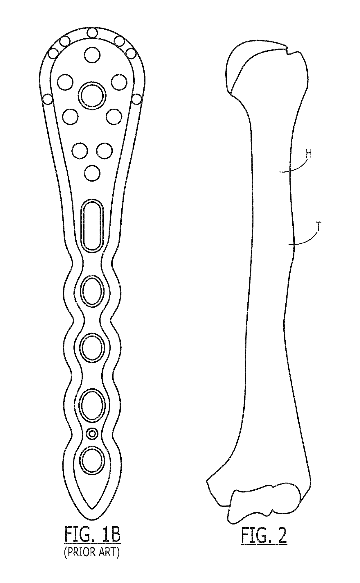
[0051]FIG. 5A illustrates a proximal humeral plate 10 for use on a patient's left shoulder. An upper section 20 has a screw hole 24 for receiving a screw to fix the proximal humerus plate to a head of the left humerus H. The trajectory of the screw hole 24 is a lateral to medial orientation. A transitional section 30 has holes 34 for receiving a screw 36 (not shown) to fix the transitional section along a lateral cortex of the humerus H. Transitional section 30 is integral with the upper section 20 and is curved sufficiently to avoid a deltoid tuberosity T (seen in FIG. 2). A lower section 40 has screw holes 44 for receiving a screw 46 (not shown), the trajectory of screw hole 44 is an anterior to posterior orientation. Lower sectio...


PUM


Abstract

A proximal humerus fracture plate for promoting healing of a fracture of a human humerus, comprising: an upper section having at least one screw hole for receiving an upper screw, the trajectory of the screw hole is a lateral to medial orientation; a transitional section having at least one screw hole for receiving a middle screw, the transitional section integral with the upper section and curved sufficiently to avoid a deltoid tuberosity, the middle screw fixing the transitional section along a lateral cortex of the humerus; and, a lower section having at least one screw hole for receiving a lower screw, the trajectory of the screw hole is an anterior to posterior orientation, the lower section integral with the transitional section.

Description

CROSS-REFERENCE TO RELATED APPLICATIONS[0001]None.STATEMENT REGARDING FEDERALLY SPONSORED RESEARCH[0002]Not Applicable.BACKGROUND OF THE INVENTION[0003]Proximal humeral fractures represent about 4-5% of all fractures and represent the third most common fracture among older patients. In many patients, the proximal humeral fracture most typically results from a fall. The damage to the humerus can be compounded by osteoporosis or an otherwise weakened bone that is found more frequently in older female patients. In younger patients, proximal humeral fractures are more likely to be a result of high-energy trauma; such as an automobile accident or a sporting injury.[0004]The majority of proximal humeral fractures are minimally or non-displaced and are generally treated non-operatively.[0005]However, operative fixation is indicated in displaced, angulated and rotated fracture patterns. Among the operative solutions commonly used for fixation are: (1) osteosuture and tension band technologi...

Claims


Application Information

Patent Timeline
Patent Type & Authority Patents(United States)
IPC IPC(8): A61B17/80A61B17/86A61B17/88
CPCA61B17/8061A61B17/86A61B17/8897A61B17/8052A61B17/8014A61B17/8894
Inventor SHAH, ANUP A.WOODY, JOSHUA T.
Owner WOODY JOSHUA DR
Why Eureka
Try Eureka