Floor nailing gun

a nailing gun and floor technology, applied in the field of tools, can solve the problems of inability to manufacture mass quantities, displacement and unevenness of nails, and easy damage to the floor, and achieve the effects of low cost, easy mass production, and simplified cross section of the nail magazin

Inactive Publication Date: 2019-04-09
TAIZHOU DAJIANG IND
View PDF32 Cites 0 Cited by
  • Summary
  • Abstract
  • Description
  • Claims
  • Application Information

AI Technical Summary

Benefits of technology

[0006]The present invention is directed to a floor nailing gun that has high nailing precision, prevents nails from trembling, and facilitates successful operation of nails.
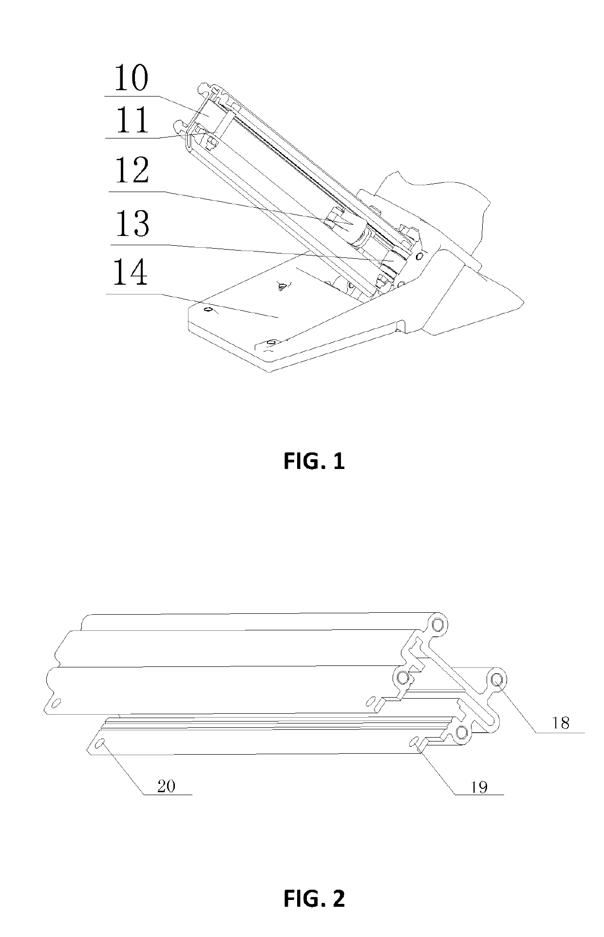
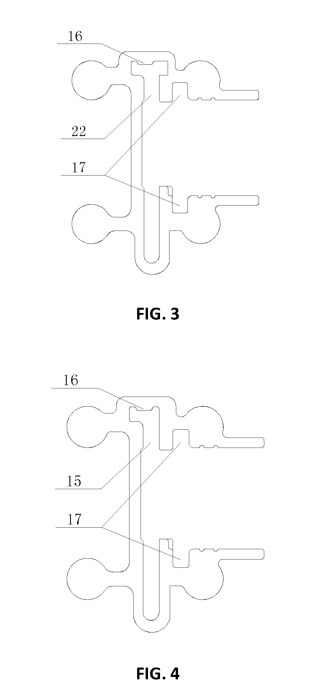
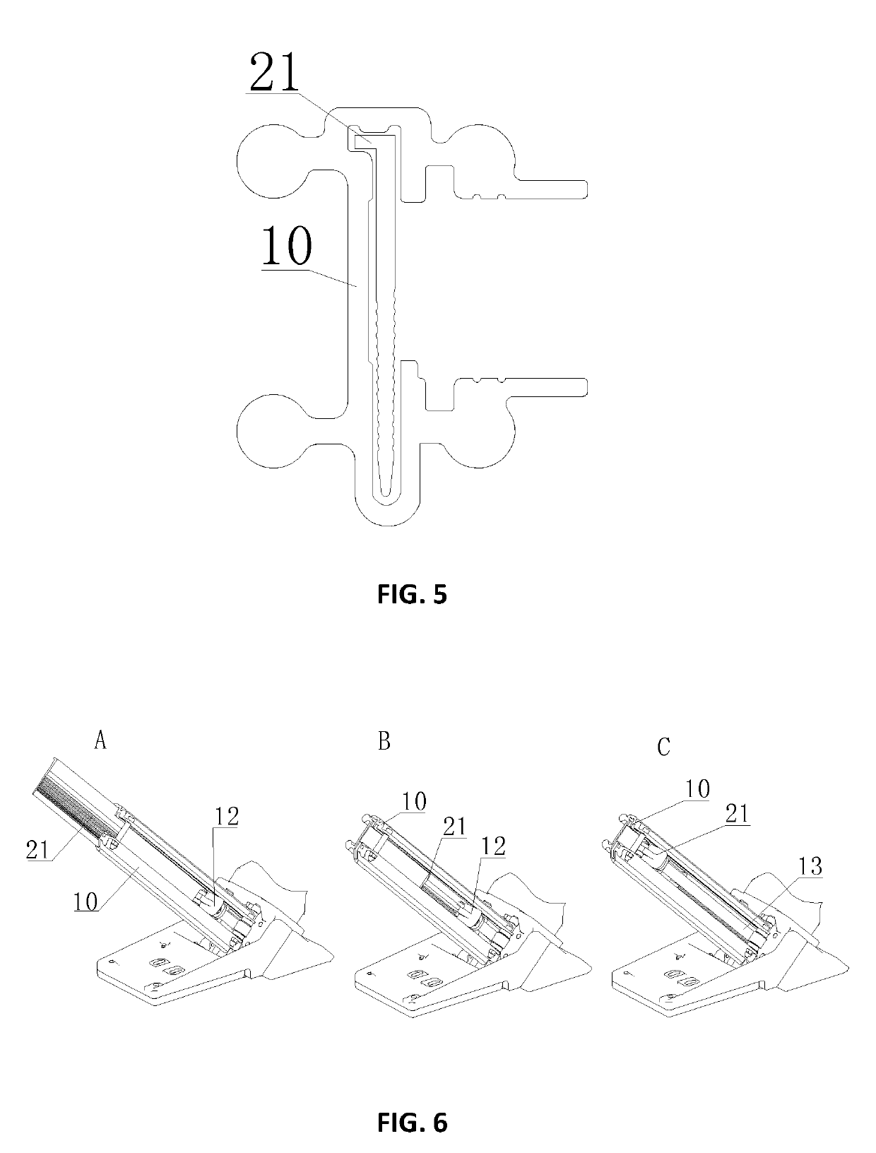
[0007]In one aspect of invention, the floor nailing gun includes a nail magazine, a sleeve component, a nail ejecting component, an elastic component, and a base, where an end face of one end of the nail magazine is provided with a threaded hole for fixedly connecting the nail magazine to the base, which facilitates assembly, and the sleeve component, the nail ejecting component, and the elastic component are mounted on the nail magazine, where the nail magazine is provided with an L-shaped groove having an L-shaped cross section or a T-shaped groove having a T-shaped cross section, a boss for preventing nails from jumping up and down is disposed at the top of the L-shaped groove or the T-shaped groove, and the boss acts on the tails of the nails, prevents error positioning of the nails caused by manufacturing of a rounded corner, and prevents a user from loading nails that are not for this tool.
[0008]In one embodiment, one side of the L-shaped groove or the T-shaped groove of the nail magazine is provided with two notches, the two notches are opposite to each other and notch openings are aligned with each other, the nail ejecting component is inserted between the two notches and slides reciprocatingly by using the two notches as a rail, and an acting end of the nail ejecting component is located in the L-shaped groove or the T-shaped groove, which facilitates nail pushing.
[0013]As compared with the conventional floor nailing guns, the floor nailing gun according to the present invention has at least the following beneficial effect: a cross section of a nail magazine is simplified, so that costs are low, mass production is easy, and restrictions on operation of small nails are facilitated; a boss at an upper end of an L-shaped groove or a T-shaped groove in the cross section of the nail magazine can effectively prevent error positioning and prevent a user from loading nails that are not for this tool, and further, the boss can prevent nails from jumping up and down, so that smooth pushing and ejection of nails are ensured, and a phenomenon of jamming and deviation of nails may not occur; therefore, a service life of the floor nailing gun is prolonged, the use effect and efficiency of the floor nailing gun are improved, and decorating effect is directly improved.

Problems solved by technology

During installation of some fragile and brittle flooring such as bamboo flooring, because nails are relatively large, the flooring can be easily damaged during installation.
However, the relatively large space of the nail slots may cause the nails to tremble in the nail slots, especially at a nail outlet of the floor nailing gun.
When a striker strikes the nails, there is a very strict requirement on a location relationship; and the displacements and unevenness of the nails is unacceptable.
Because the displacements and unevenness of the nails may cause faults such as jamming of the floor nailing gun or deviation of the nails, a lifetime of the floor nailing gun is reduced, the use effect and efficiency of the floor nailing gun are affected, and decorating effect is directly affected.
Therefore, heretofore unaddressed needs exist in the art to address the aforementioned deficiencies and inadequacies.

Method used


Image

  • Floor nailing gun
  • Floor nailing gun
  • Floor nailing gun

Examples


Embodiment Construction

[0023]The present invention will now be described more fully hereinafter with reference to the accompanying drawings, in which exemplary embodiments of the invention are shown. This invention may, however, be embodied in many different forms and should not be construed as limited to the embodiments set forth herein. Rather, these embodiments are provided so that this disclosure will be thorough and complete, and will fully convey the scope of the invention to those skilled in the art. Like reference numerals refer to like elements throughout.

[0024]It will be understood that when an element is referred to as being “on” another element, it can be directly on the other element or intervening elements may be present therebetween. In contrast, when an element is referred to as being “directly on” another element, there are no intervening elements present. As used herein, the term “and / or” includes any and all combinations of one or more of the associated listed items.

[0025]It will be und...


PUM


Abstract

In one aspect of the invention, a floor nailing gun includes a nail magazine; a sleeve component; a nail ejecting component; an elastic component; and a base, where an end face of one end of the nail magazine is provided with at least one threaded hole for fixedly connecting the nail magazine to the base, and the sleeve component, the nail ejecting component, and the elastic component are mounted on the nail magazine, wherein the nail magazine is provided with an L-shaped groove having an L-shaped cross section or a T-shaped groove having a T-shaped cross section, and a boss for preventing nails from jumping up and down is formed at the top of the L-shaped groove or the T-shaped groove.

Description

CROSS-REFERENCE TO RELATED APPLICATIONS[0001]This application is a continuation application of International Patent Application No. PCT / CN2013 / 087552, filed Nov. 21, 2013, which itself claims the priority to Chinese Patent Application No. 201320713892.0, filed Nov. 12, 2013 in the State Intellectual Property Office of P.R. China, which are hereby incorporated herein in their entireties by reference.FIELD OF THE INVENTION[0002]The present invention relates generally to tools, and more particularly, to a floor nailing gun.BACKGROUND OF THE INVENTION[0003]The background description provided herein is for the purpose of generally presenting the context of the present invention. The subject matter discussed in the background of the invention section should not be assumed to be prior art merely as a result of its mention in the background of the invention section. Similarly, a problem mentioned in the background of the invention section or associated with the subject matter of the backgro...

Claims


Application Information

Patent Timeline
Patent Type & Authority Patents(United States)
IPC IPC(8): B25C1/00B25C1/04B25C3/00E04F21/22B25C1/18B25C5/16
CPCE04F21/22B25C1/005B25C1/04B25C3/00B25C5/1658B25C1/184B25C5/1637B25C5/1644
Inventor YANG, MING-JUNZHU, ZAI-JUN
Owner TAIZHOU DAJIANG IND
Why Eureka
Try Eureka