System and method for making a carcass for a pneumatic vehicle tire

arcass technology, applied in the field of making a carcass for a pneumatic vehicle tire, can solve the problems of high machinery expenditure, and achieve the effect of efficient and cost-saving manufactur

Active Publication Date: 2019-04-23
CONTINENTAL REIFEN DEUTSCHLAND GMBH
View PDF19 Cites 0 Cited by
  • Summary
  • Abstract
  • Description
  • Claims
  • Application Information

AI Technical Summary

Benefits of technology

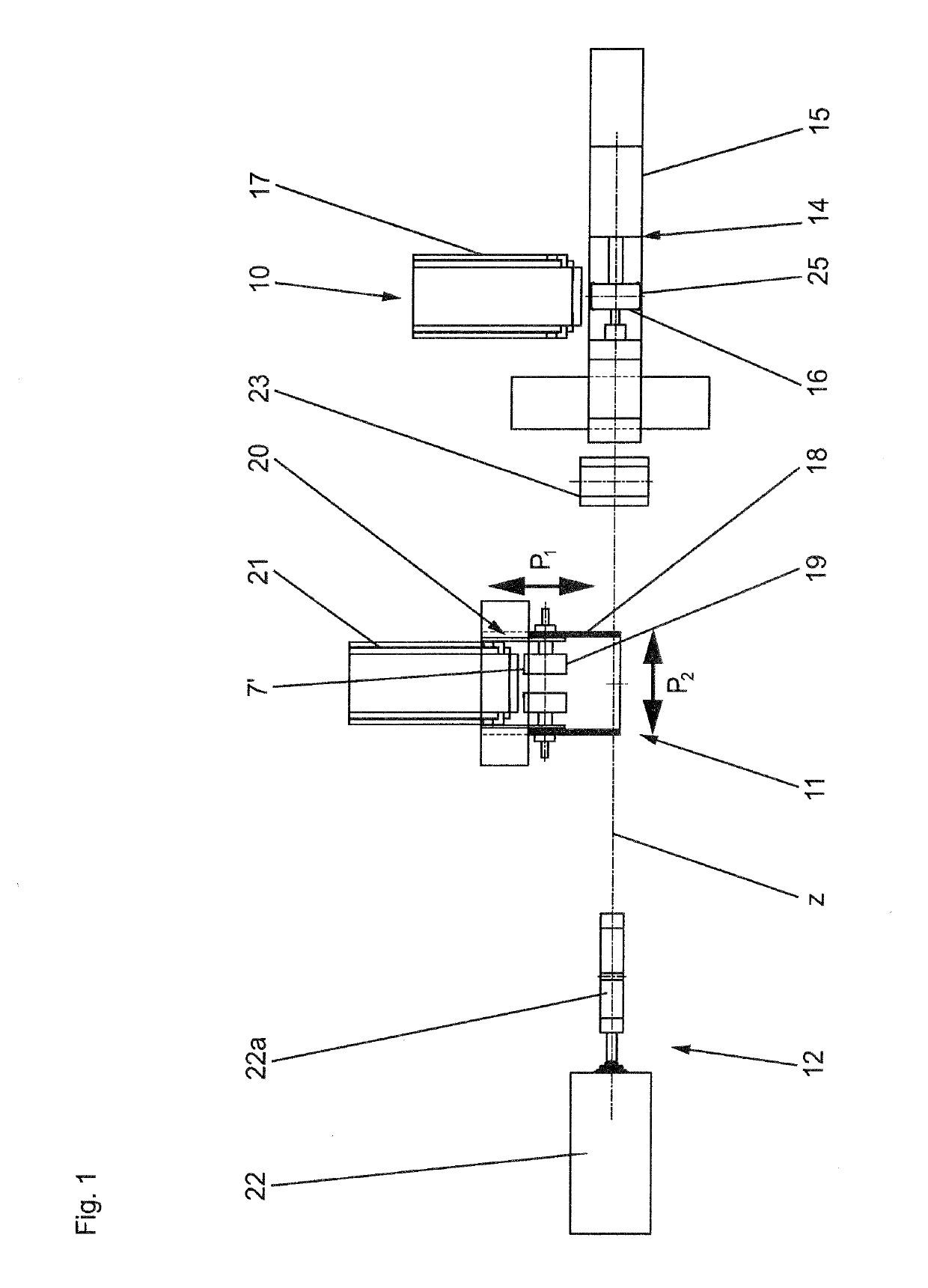
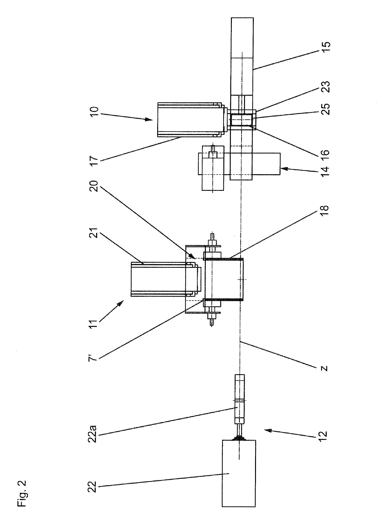
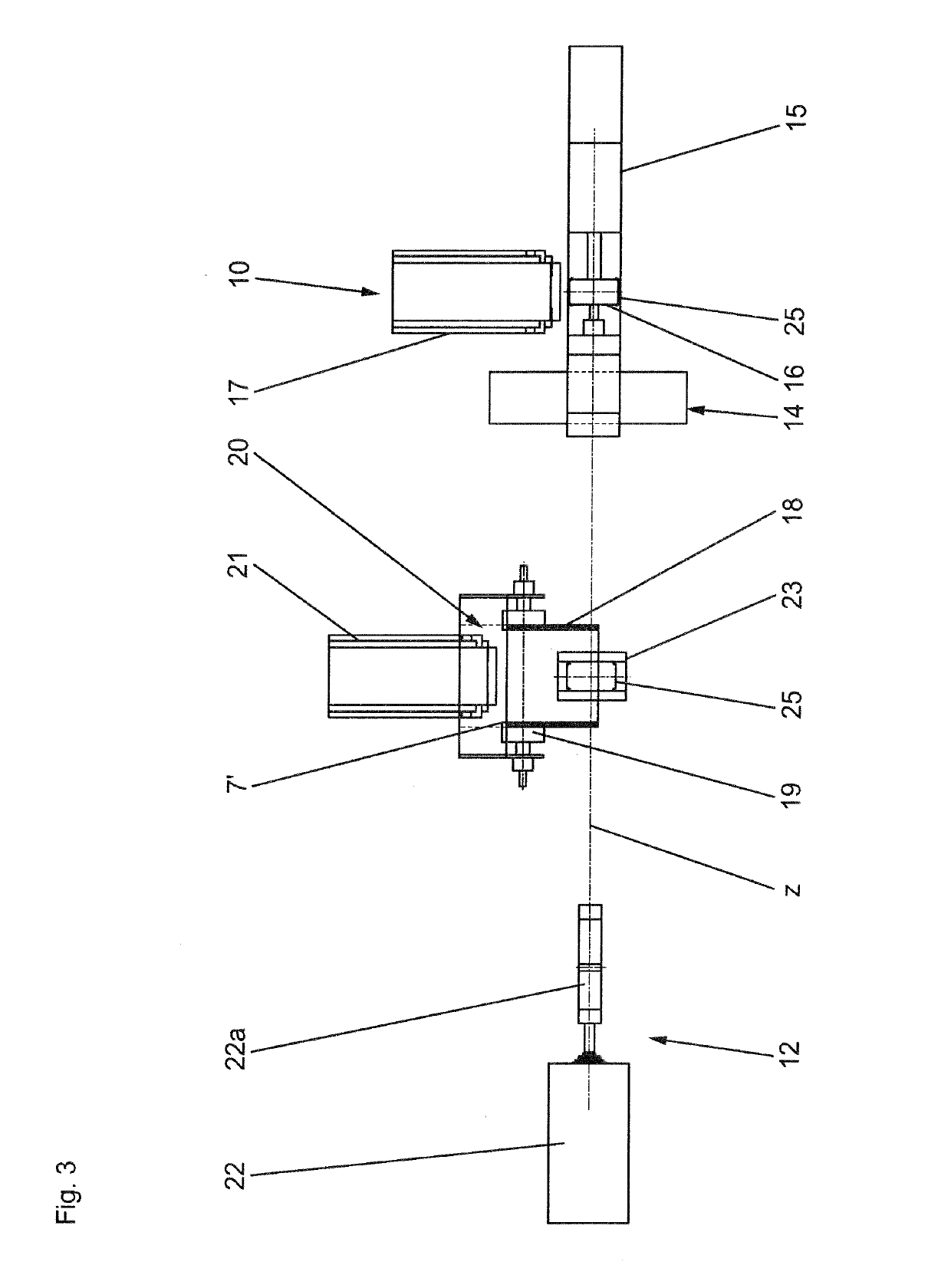
[0012]According to the invention, the carcass therefore remains on a single transfer device, starting with its being built up without sidewalls, to the point where it is transferred to the shaping machine. Time-consuming transfer steps to different devices involving a high outlay on machinery are thus eliminated. While the carcass produced is being transferred and provided with the sidewalls, the next carcass can already be in the process of being built up at the carcass station of the system. It is therefore possible to produce tire carcasses very efficiently and in a time-saving and cost-saving manner by means of the invention.
[0013]The method is particularly efficient and time-saving if the sidewalls are applied as annularly encircling mixture strips on sidewall drums by a sidewall servicer at a separate sidewall station, the transfer device together with the carcass is moved in front of the sidewall station, the sidewall drums are moved coaxially up to the carcass for the purpose of tacking on the sidewalls and, after the sidewalls have been tacked on, are moved away from the carcass. The sidewalls have therefore already been prepared as annularly encircling components on the sidewall drums when the transfer device together with the carcass is being moved to the sidewall station.
[0015]For a simple structural embodiment of the transport apparatus for the transfer device, it is advantageous if the transfer device is moved from the carcass station to the shaping machine along a linear transfer path.
[0019]In this alternative according to the invention too, the carcass is transferred to a transfer device just once. This method and this system therefore likewise allow efficient and cost saving manufacture of tire carcasses of different configurations.

Problems solved by technology

This prejudices efficient progress of the buildup process and the outlay on machinery is high.

Method used


Image

  • System and method for making a carcass for a pneumatic vehicle tire
  • System and method for making a carcass for a pneumatic vehicle tire
  • System and method for making a carcass for a pneumatic vehicle tire

Examples


Embodiment Construction

[0024]The method according to the invention relates to the production of any pneumatic vehicle tire of radial construction, especially for passenger vehicles. In the description of the buildup method with reference to FIGS. 1 to 9, mention is made of tire components which are for the most part not shown in FIGS. 1 to 9. These components and the positioning thereof in the finished pneumatic vehicle tire will now be explained by way of example with reference to FIG. 10.

[0025]The radial pneumatic tire shown in FIG. 10 has an airtight inner liner 1, a carcass inlay 2, bead regions with bead cores 3 and core fillers 4, a belt consisting of a plurality of belt plies 5 and a belt bandage 6, and furthermore sidewalls 7 and a tread rubber 8. The carcass inlay 2 consists of one ply or a plurality of plies of textile or metal cords, which are embedded in a known manner in a rubber mixture and extend at least substantially in a radial direction from bead region to bead region. The end portions ...


PUM

PropertyMeasurementUnit
lengthsaaaaaaaaaa
timeaaaaaaaaaa
durableaaaaaaaaaa

Abstract

A method for making a carcass for a pneumatic vehicle tire includes building up a carcass free from sidewalls with an inner liner, a single-ply or multi-ply carcass inlay and bead cores, at a carcass station on a carcass building drum, while creating ply turnups. The carcass produced without sidewalls is transferred to a transfer device. The carcass is kept on the transfer device while applying sidewalls to the carcass. The carcass is retained on the transfer device while transferring the carcass provided with the sidewalls to a shaping machine where the carcass is shaped into a toroidal shape.

Description

CROSS REFERENCE TO RELATED APPLICATIONS[0001]This application is a continuation application of international patent application PCT / EP2014 / 052276, filed Feb. 6, 2014, designating the United States and claiming priority from German application 10 2013 103 633.3, filed Apr. 11, 2013, and the entire content of both applications is incorporated herein by reference.FIELD OF THE INVENTION[0002]The invention relates to a method for making a carcass for a pneumatic vehicle tire. The tire is assembled with a belt assembly and a tread rubber to form the finished green tire. The method includes the steps of:[0003]building up a carcass free from sidewalls with an inner liner, a single-ply or multi-ply carcass inlay, bead cores, in particular with bead fillers, at a carcass station on a carcass building drum, while creating the ply turnups;[0004]applying the sidewalls to the carcass;[0005]transferring the carcass provided with the sidewalls to a shaping machine; and,[0006]shaping the carcass int...

Claims


Application Information

Patent Timeline
Patent Type & Authority Patents(United States)
IPC IPC(8): B29D30/72B29D30/26B29D30/30B29D30/20
CPCB29D30/72B29D30/2607B29D30/3014B29D30/3028B29D2030/202
Inventor THOMFOHRDE, CLAUDIAREITMANN, SEBASTIANLINNE, STEFANKNEUSSEL, EWALDMOELLER, CHRISTIAN
Owner CONTINENTAL REIFEN DEUTSCHLAND GMBH
Why Eureka
Try Eureka