Rotor of permanent magnet-type rotary electric machine

a rotary electric machine and permanent magnet technology, applied in the direction of dynamo-electric machines, magnetic circuit rotating parts, magnetic circuit shape/form/construction, etc., can solve problems such as noise and collision, and achieve the effect of preventing a decrease of the magnetic characteristic of the rotor

Active Publication Date: 2019-05-07
FUJI ELECTRIC CO LTD
View PDF16 Cites 0 Cited by
  • Summary
  • Abstract
  • Description
  • Claims
  • Application Information

AI Technical Summary

Benefits of technology

[0011]According to the rotor of the permanent magnet-type rotary electric machine according to the present invention, at least one endplate out of the pair of endplates is provided with the pressing portion configured to abut with the outer peripheral side of one axial end of the rotor core to apply a pressing force toward the other end plate. Accordingly, even when plate thicknesses of the laminated electromagnetic steel sheets are uneven, it is possible to surely eliminate a space on the outer peripheral side of the electromagnetic steel sheets and prevent a decrease of a magnetic characteristic of the rotor.

Problems solved by technology

Accordingly, at the time when the rotor rotates or stops, the permanent magnets in the rotor slots may move to cause collision noise.

Method used


Image

  • Rotor of permanent magnet-type rotary electric machine
  • Rotor of permanent magnet-type rotary electric machine
  • Rotor of permanent magnet-type rotary electric machine

Examples


first embodiment

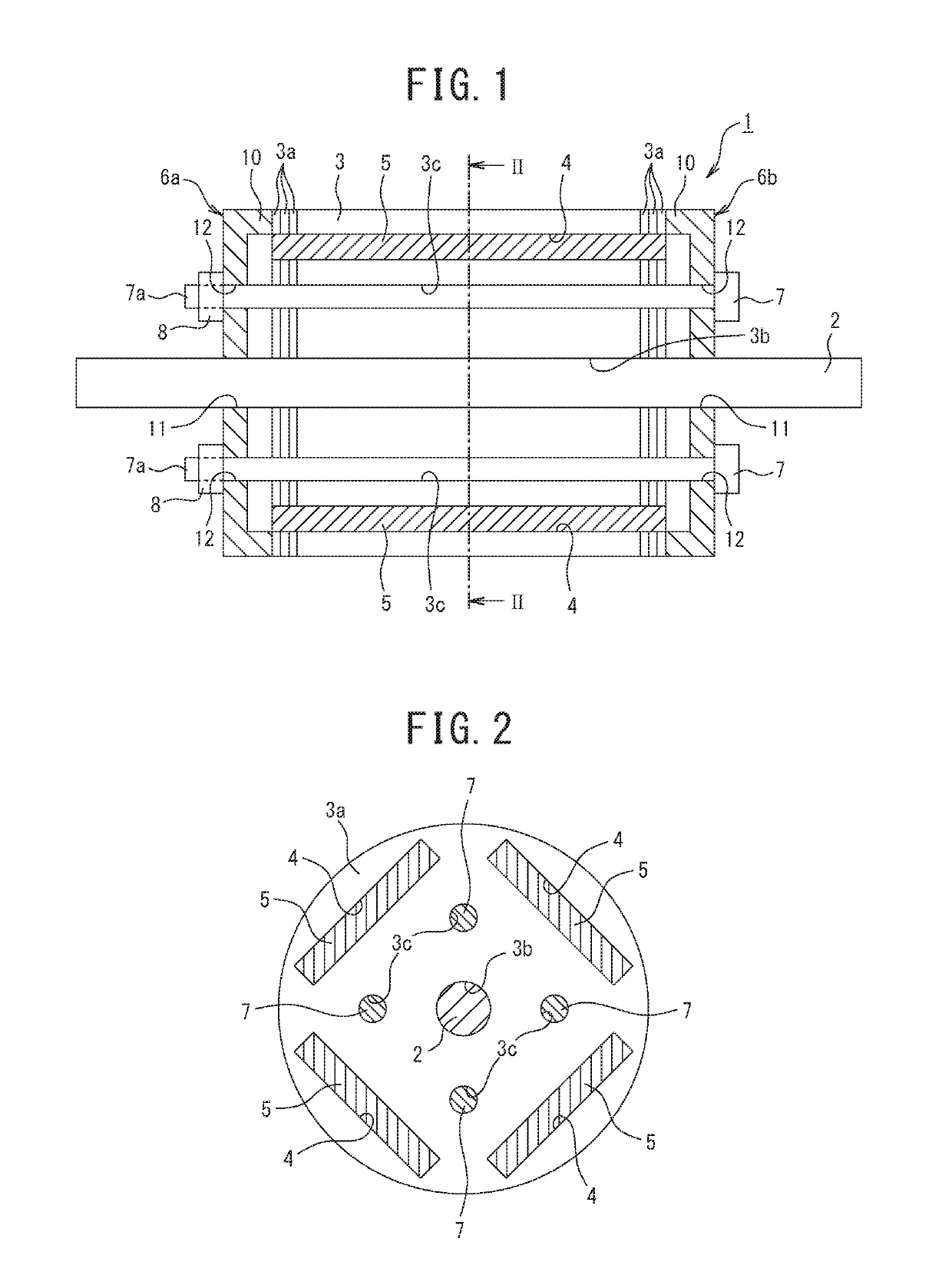
[0026]FIGS. 1 to 3 illustrate a rotor 1 of a permanent magnet-type rotary electric machine according to a first embodiment. The permanent magnet-type rotary electric machine includes a stator (not illustrated), and the rotor 1 placed in a rotatable manner via a gap from an inner peripheral surface of the stator.

[0027]As illustrated in FIGS. 1 and 2, the rotor 1 includes: a rotating shaft 2; a rotor core 3 through which the rotating shaft 2 penetrates so as to be fixed thereto in an integrally rotatable manner; a plurality of rotor slots 4 provided at regular intervals in a circumferential direction of an inside of the rotor core 3 and formed to penetrate therethrough in an axial direction; a plurality of permanent magnets 5 inserted into the rotor slots 4; a pair of end plates 6a, 6b placed at both axial ends of the rotor core 3; a plurality of clamping bolts 7 placed to penetrate through the rotor core 3 and the pair of end plates 6a, 6b; and nuts 8 screwed onto threaded portions 7...

second embodiment

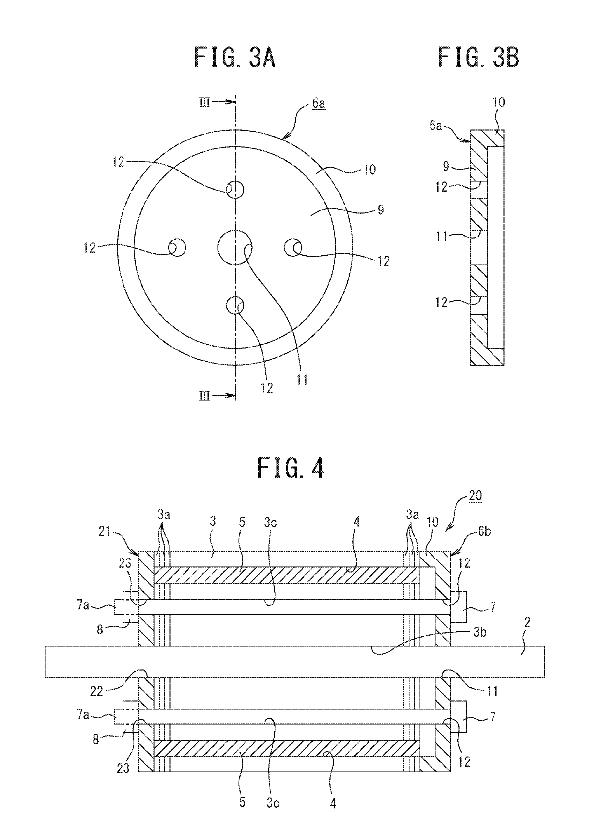
[0034]Subsequently, FIG. 4 illustrates a rotor 20 of a permanent magnet-type rotary electric machine according to the second embodiment in which some members have different configurations from the rotor 1 of the permanent magnet-type rotary electric machine according to the first embodiment.

[0035]In the rotor 20 of the second embodiment, a discoid end plate 21 is placed at one axial end of a rotor core 3. The discoid end plate 21 has generally the same outer shape as electromagnetic steel sheets 3a constituting the rotor core 3, and a shaft through hole 22 through which a rotating shaft 2 penetrates, and a plurality of bolt through holes 23 through which clamping bolts 7 penetrate are formed. Further, an end plate 6b having the same structure as the first embodiment is placed at the other axial end of the rotor core 3.

[0036]The clamping bolts 7 are passed through the bolt through holes 23, 12 of the end plates 21, 6b placed at both axial ends of the rotor core 3 and bolt through hol...

third embodiment

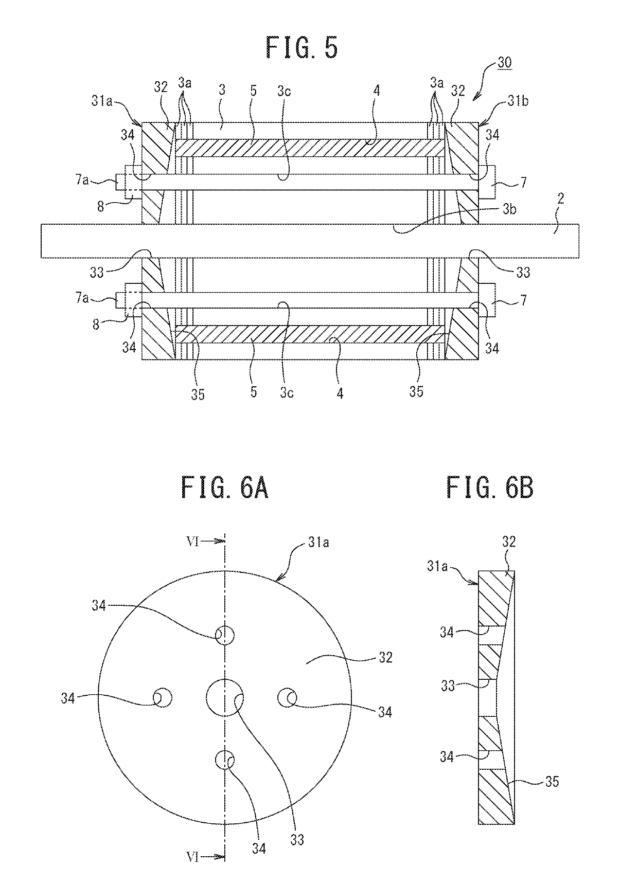
[0038]Subsequently, FIGS. 5 and 6 illustrate a rotor 30 of a permanent magnet-type rotary electric machine according to a third embodiment.

[0039]The rotor 30 according to the third embodiment is different from the rotor 1 of the permanent magnet-type rotary electric machine according to the first embodiment in the structure of the end plates.

[0040]In the rotor 30 of the third embodiment, a pair of end plates 31a, 31b are placed at both axial ends of a rotor core 3.

[0041]As illustrated in FIGS. 6A, 6B, one end plate 31a out of the pair of endplates 31a, 31b includes: a circular plate portion 32 having generally the same outer shape with electromagnetic steel sheets 3a constituting the rotor core 3; a shaft through hole 33 formed in a center of the circular plate portion 32 so that a rotating shaft 2 penetrates therethrough, and a plurality of bolt through holes 34 formed around the shaft through hole 33 so that clamping bolts 7 penetrate therethrough.

[0042]One surface, in a plate-thi...


PUM


Abstract

Provided is a rotor (1) of a permanent magnet-type electric rotary machine, the rotor being able to restrain a decrease of a magnetic characteristic. A pair of endplates (6a, 6b) placed at both axial ends of a rotor core (3) are each provided with a pressing portion (10, 10) configured to abut with an outer peripheral side of an end of the rotor core (3) to apply a pressing force toward the other end plate.

Description

CROSS-REFERENCE TO RELATED APPLICATIONS[0001]This application is a U.S. National Stage Application, which claims the benefit under 35 U.S.C. § 371 of PCT International Patent Application No. PCT / JP2015 / 002402, filed May 12, 2015, which claims the foreign priority benefit under 35 U.S.C. § 119 of Japanese Patent Application No. 2014-118798, filed Jun. 9, 2014, the contents of which are incorporated herein by reference.TECHNICAL FIELD[0002]The present invention relates to a rotor of a permanent magnet-type rotary electric machine, the rotor being placed in a rotatable manner via a gap from an inner peripheral surface of a stator.BACKGROUND ART[0003]A rotor of a permanent magnet-type rotary electric machine is configured by laminating a plurality of electromagnetic steel sheets, and includes: a rotor core fixed so as to rotate integrally with a rotating shaft penetrating therethrough; a plurality of rotor slots provided at regular intervals in a circumferential direction of the rotor c...

Claims


Application Information

Patent Timeline
Patent Type & Authority Patents(United States)
IPC IPC(8): H02K1/27H02K1/28H02K15/03
CPCH02K15/03H02K1/28H02K1/2706H02K1/276
Inventor MAE, KENICHIMOCHIDA, TOSHIHARUSHUTO, MASAONISHIMURA, HIROFUMI
Owner FUJI ELECTRIC CO LTD
Why Eureka
Try Eureka