

Phosphor material and light-emitting device
A technology for light-emitting devices and phosphors, applied in the field of light-emitting devices and phosphor materials, can solve problems such as the reduction of light-emitting properties, and achieve the effects of high properties, prevention of degradation of properties, and excellent properties.
- Summary
- Abstract
- Description
- Claims
- Application Information
AI Technical Summary
Problems solved by technology
Method used
Image

Examples
Embodiment 1
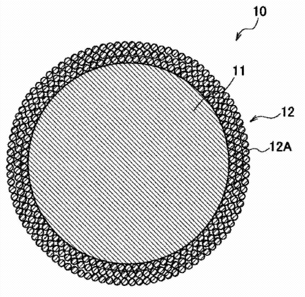
[0054] Prepare the yttrium oxide (Y) with an average particle diameter of 20 nm and a maximum particle diameter of 50 2 o 3 ) particles 12A dispersed in a solvent, and green phosphor particles 11 with an average particle diameter of about 10 μm are mixed in the slurry, and then the slurry is coated on the surface of phosphor particles 11 . Then, the phosphor particles 11 coated with the slurry are heat-treated to be dried. The heat treatment was performed at 300° C. for 2 hours in the air, or at 400° C. for 2 hours in a nitrogen atmosphere. Next, for the dried phosphor particles 11 , the slurry coating step and the drying step are repeated in the same manner to obtain the phosphor material 10 .
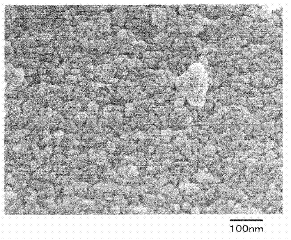
[0055] image 3 An example of a SEM (Scanning Electron Microscope: Scanning Electron Microscope) photograph showing the obtained phosphor material 10; Figure 4 An example of an SEM photograph of phosphor particles 11 before forming coating layer 12 is shown. also, Figure 5 An ...
Embodiment 2-1 to 2-4、 comparative example 2-1
[0065] The phosphor material 10 and the light emitting device 20 were produced in the same manner as in Example 1 except that the average particle diameter and the maximum particle diameter of the microparticles 12A were changed. In embodiment 2-1, the average particle diameter used is 40nm, and the maximum particle diameter is 50nm. In embodiment 2-2, the average particle diameter is 30nm, and the maximum particle diameter is 50nm. Diameter is 25nm, and maximum particle diameter is 50nm, and using average particle diameter in embodiment 2-4 is 20nm, and maximum particle diameter is 40nm, and using average particle diameter in comparative example 2-1 is 50nm, and maximum particle diameter is 80nm Particle 12A. A light-emitting test was performed on the obtained light-emitting device 20 in the same manner as in Example 1, and temporal changes in luminance were studied. The obtained results are shown in Table 1 together with the results of Example 1 and Comparative Examples 1-1...
Embodiment 3
[0071] The phosphor material 10 and the light-emitting device 20 were manufactured in the same manner as in Example 1 except that the slurry coating step and the drying step were performed only once. When the obtained phosphor material 10 was observed by TEM, it was confirmed that the covering layer 12 was formed on the entire surface of the phosphor particles 11 . In addition, the covering layer 12 has a structure in which fine particles 12A are interlayered from one particle layer to three particle layers on average. Figure 9A TEM photograph showing the vicinity of the surface of the obtained phosphor material 10 is shown. In addition, the obtained light-emitting device 20 was also subjected to a light-emitting test in the same manner as in Example 1 to examine changes in luminance over time. The obtained results are then shown in Table 2 and the results of Example 1 and Comparative Example 1-1. Figure 10 . In Table 2 and Figure 10 In , the luminance maintenance rate ...
PUM
| Property | Measurement | Unit |
|---|---|---|
| particle size | aaaaa | aaaaa |
| particle size | aaaaa | aaaaa |
| thickness | aaaaa | aaaaa |
Abstract
Description
Claims
Application Information