Motor

A technology for electric motors and electric vehicles, applied in the field of electric motors, can solve problems such as characteristic degradation, affecting motor noise, vibration, permanent magnet magnetic flux leakage, etc., to achieve the effects of reducing noise, high speed, and reducing torque ripple

Inactive Publication Date: 2006-04-05
PANASONIC CORP
View PDF2 Cites 1 Cited by
  • Summary
  • Abstract
  • Description
  • Claims
  • Application Information

AI Technical Summary

Problems solved by technology

[0004] However, in JP-A-9-294362, there is a problem that the above-mentioned motor is only a combination of dissimilar rotors, and cannot prevent deterioration of characteristics due to interaction.
In other words, there is a problem that when one rotor with permanent magnets is used, and the other core covers the permanent magnets, the magnetic flux of the permanent magnets leaks to the other rotor, resulting in deterioration of characteristics.
[0005] In Japanese Patent Application Laid-Open No. 7-59310, since a non-magnetic material is interposed when connecting dissimilar rotors in the axial direction, the characteristic drop caused by magnetic flux leakage is suppressed, but the interposition of a non-magnetic material brings problems of increase in size and cost.
Combining dissimilar rotors at a predetermined angle in the direction of rotation can reduce torque ripple. However, the cog torque of the permanent magnets causes torque ripple and affects the noise and vibration of the motor. Therefore, when at least one of the dissimilar rotors has When the torque is large, as a result, the effect of reducing the noise and vibration of the motor cannot be obtained sufficiently

Method used


Image

  • Motor
  • Motor
  • Motor

Examples


Embodiment Construction

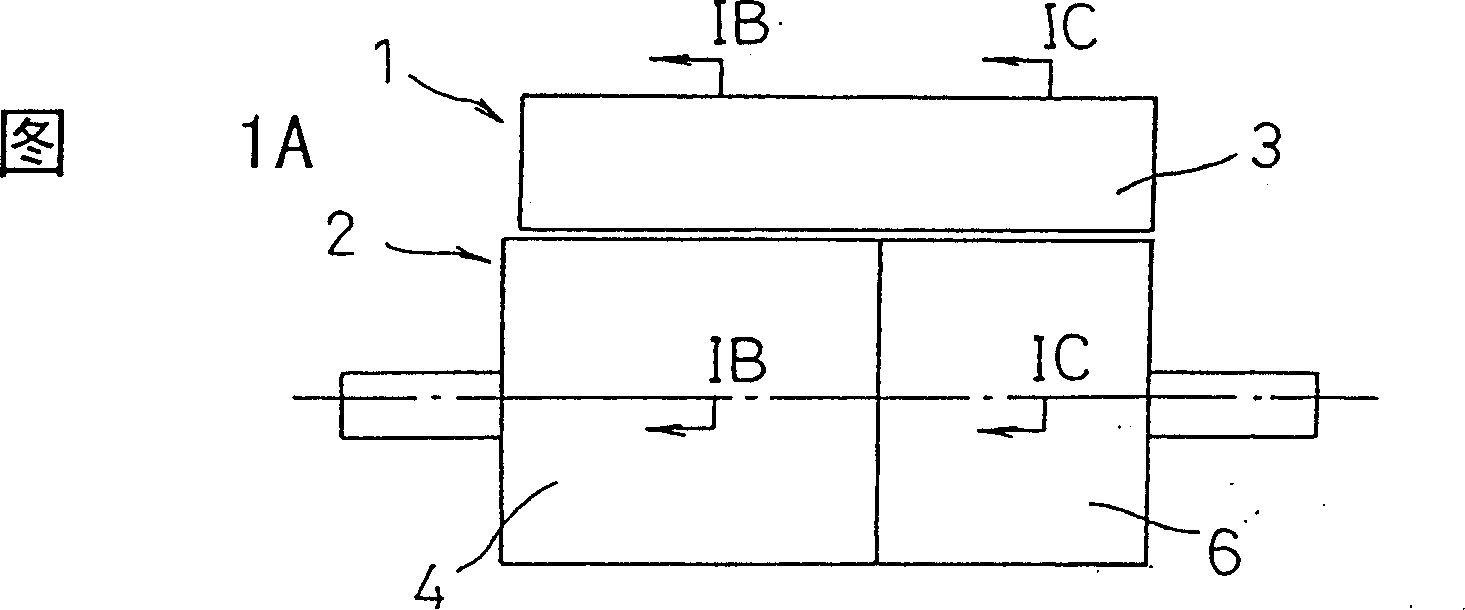
[0033] Hereinafter, a first embodiment of the motor according to the present invention will be described with reference to FIGS. 1 and 2 . The overall structure of the motor and its combination Figure 12 The descriptions made are the same, so only the main parts of the present invention will be described here.

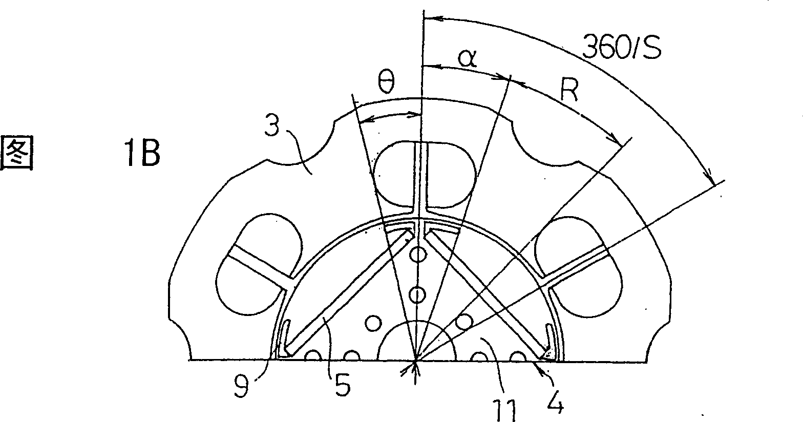
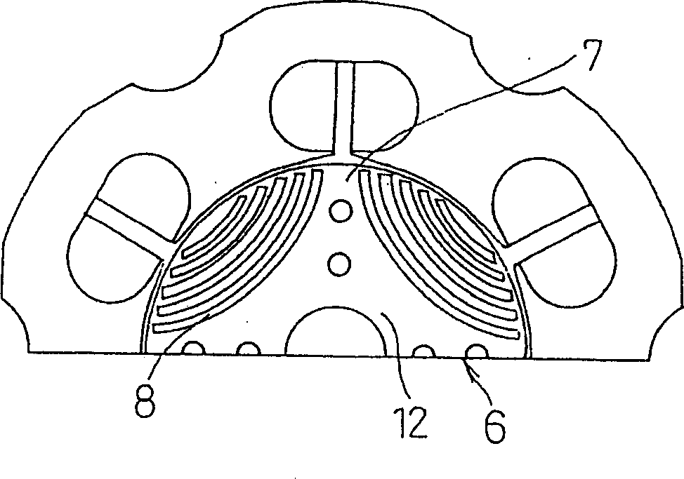
[0034] 1A shows a part of the rotor 2 and the stator 3 of the motor 1, and the rotor 2 of the motor 1 is composed of a permanent magnet type rotor part 4 and a permanent magnet type rotor part 4 shown in FIG. 1B. Figure 1C The shown reluctance type rotor part 6 is constituted. The permanent magnet type rotor part 4 is embedded with four (2n, n=2) rare-earth magnets or iron oxides inside the rotor core 11 formed by laminating roughly circular rotor core plates formed by punching electromagnetic steel sheets. The permanent magnet 5 such as a body magnet is constituted. N poles and S poles of each permanent magnet 5 are alternately arranged in the circumferential dire...


PUM


Abstract

A motor (1, 31) comprising: a. rotor (2, 32) including a permanent magnet type rotor unit (4, 34) having a plurality of permanent magnets (5, 35) and a reluctance type rotor unit (6, 36) having a plurality of magnetic salient pole portions (7, 37) and a plurality of slits (8, 38) for preventing flux leakage, the rotor units (4, 34, 6, 36) being coupled to each other in an axial direction; and a stator (3, 33) for generating a field for driving the rotor (2, 32). Elongated holes (9) or notches (9a) for preventing the short-circuit of magnetic fluxes are arranged near edges of the permanent magnet (5, 35) of the permanent magnet type rotor unit (4, 34). The elongated holes (9) or the notches (9a) are arranged within a range defined so that 0.95 alpha H02K 1 / 27 H02K 1 / 12 14 9 2 2002 / 8 / 29 1409459 2003 / 4 / 9 1249884 2006 / 4 / 5 2006 / 4 / 5 2006 / 4 / 5 Matsushita Electric Industrial Co., Ltd. Japan Tame Masaki Kondo Yasuhiro liu libeng 31100 Shanghai Patent Agency Building 34--35, No.2650 Zhongshan North Road, Shanghai 200063 Japan 2001 / 8 / 29 2001-259788 Japan 2002 / 6 / 28 2002-189581

Description

technical field [0001] The invention relates to an electric motor, in particular to an electric motor in a synchronous electric motor, and the electric motor reduces noise and vibration through a combination of rotor structures. Background technique [0002] Japanese Unexamined Patent Publication No. 9-294362 discloses a synchronous motor in which a rotor of different types is connected in the axial direction to increase the degree of freedom in design. Below, combine Figure 12 The motor 1 is composed of a permanent magnet type rotor portion 4 arranged with a plurality of permanent magnets and a reluctance type rotor portion 6 forming a plurality of salient pole portions to connect a rotor 2 in the axial direction, and generates a magnetic field for rotationally driving the rotor 2. The stator 3 constitutes. [0003] Japanese Patent Laid-Open No. 7-59310 discloses such a motor: the motor is clamped with a non-magnetic body in the axial direction to connect dissimilar rotor...

Claims


Application Information

Patent Timeline
Patent Type & Authority Patents(China)
IPC IPC(8): H02K1/27H02K1/12H02K16/00H02K16/02H02K19/06H02K19/10H02K21/14
CPCH02K1/2786B60L2220/14B60L15/20B60L2210/10B60L11/1803B60L2270/145B60L11/14B60L11/1887H02K16/02H02K1/276B60L2240/423H02K1/246B60L2220/18B60L2240/421B60L2270/142H02K21/14B60L2210/40Y02T10/70B60L50/16B60L50/51B60L58/40Y02T10/64Y02T10/72Y02T10/7072H02K1/2791Y02T90/40
Inventor 田米正树近藤康宏
Owner PANASONIC CORP
Why Eureka
Try Eureka