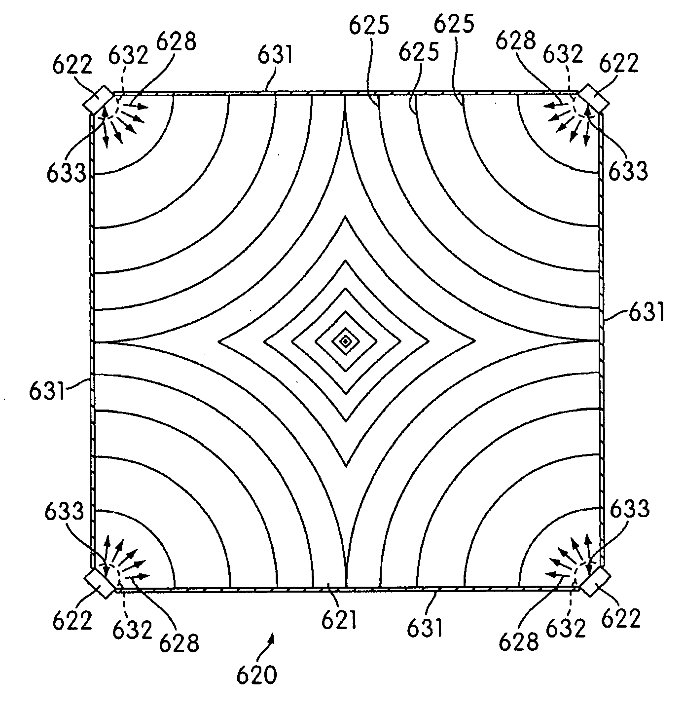
[0014]According to the invention a light emitting panel comprises: a polygonal-shaped light guiding medium having a light emitting face, an opposite face and truncated corners, at least one
light source associated with each truncated corner of the light guiding medium and configured to couple light into the associated truncated corner and a pattern of features on at least one face of the light guiding medium for promoting emission of light from the light emitting face, said pattern of features being configured such that a variation in emitted
light intensity over substantially the entire surface of the light emitting face is less than or equal to about 25%. A particular
advantage of the invention is that fewer relatively
higher power light sources, typically LEDs or LED arrays, can be utilized thereby reducing cost and at the same time a substantially uniform
emission intensity achieved using an appropriate surface patterning of the light guiding medium. By careful configuration of the pattern of features the intensity of hot spots can be reduced and the dark region in the center of the panel reduced.
[0015]In typical applications of the invention such as general lighting or back-lighting of
liquid crystal displays, the light guiding medium will be square or rectangular in shape and for such applications only four LEDs / LED arrays will be required in which one is associated with a respective corner of the light guiding medium.
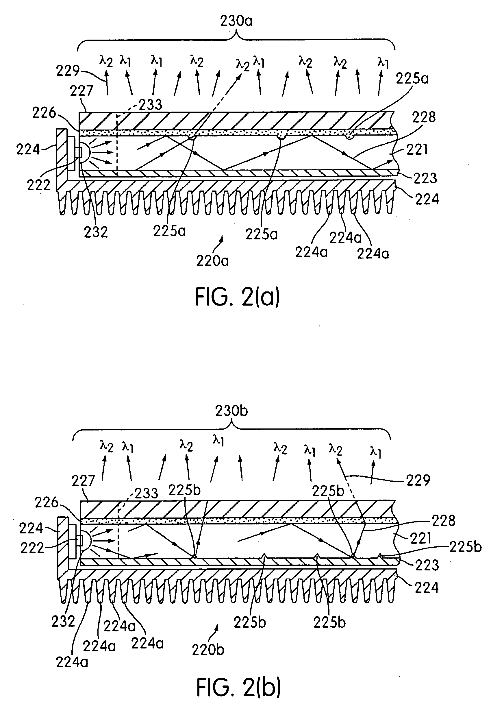
[0016]The pattern of features can be configured, at least in part, in dependence on a light intensity distribution within the light guiding medium which can be calculated or derived empirically. Since the light distribution is non-uniform and will vary with distance from each light source, the spacing of features can depend on the distance from each light source. Typically, the spacing will reduce as the intensity falls with increasing distance from each light source. Alternatively and / or in addition the size and / or shape of the features can depend upon the distance from each light source. Moreover, the pattern can also be configured such that the number of features per unit area increases in dependence on distance from each light source.
[0017]To maximize
coupling of light into the light guiding medium at least one substantially hemispherical (dish-shaped) indentation in an edge of the light guiding medium is associated with each light source in which the indentations are provided in the truncated corners of the light guiding medium and wherein the associated light source is positioned at substantially the center of the indentation. The indentations are configured, that is their curvature and / or
diameter, such as to maximize the proportion of light from the associated light source that strikes the surface of the indentation at substantially normal incidence and thereby maximizes
coupling of light into the light guiding medium.
[0018]In one arrangement the features are formed as an integral part of the light guiding medium, by for example precision molding the light guiding medium. Alternatively, and / or in addition the face of the light guiding medium can be processed to define the features by for example selectively mechanically abrading,
grinding, milling, scribing,
etching, blasting with
abrasive particles or
laser ablating the face of the light guiding medium. In a further arrangement the features can be applied to the face of the light guiding medium by for example
screen printing features that comprise a material with a different index of
refraction to that of the light guiding medium. Preferably such features have a
refractive index that is similar to or lower than the light guiding medium to provide a degree of index matching.
[0019]Typically, when the features are applied to the face of the
light guide they will be essentially 2-dimensional in form and can comprise for example lines (straight or curved), substantially circular; substantially elliptical, substantially polygonal, substantially triangular, substantially square, substantially rectangular or substantially hexagonal shaped features. Alternatively, the features can be 3-dimensional in form and project into, or extend out of, the face of the light guiding medium. Such features can comprise many forms including, for example, features that are ridges (e.g. u- or v-shaped), grooves (e.g. u- or v-shaped), substantially hemispherical features, substantially pyramidal features, substantially tetrahedral features or substantially trapezohedral features.

