Regulation of Wavelength Shift and Perceived Color of Solid State Lighting with Intensity and Temperature Variation

a technology of intensity and temperature variation, applied in the field of power conversion, can solve the problems of inaccurate control of intensity, limitation of intensity variation depth, and creation of electromagnetic interference (“emi”), and achieve the effects of reducing cost and size, increasing efficiency, and increasing efficiency

Active Publication Date: 2009-03-26
CHEMTRON RES
View PDF49 Cites 129 Cited by
  • Summary
  • Abstract
  • Description
  • Claims
  • Application Information

AI Technical Summary

Benefits of technology

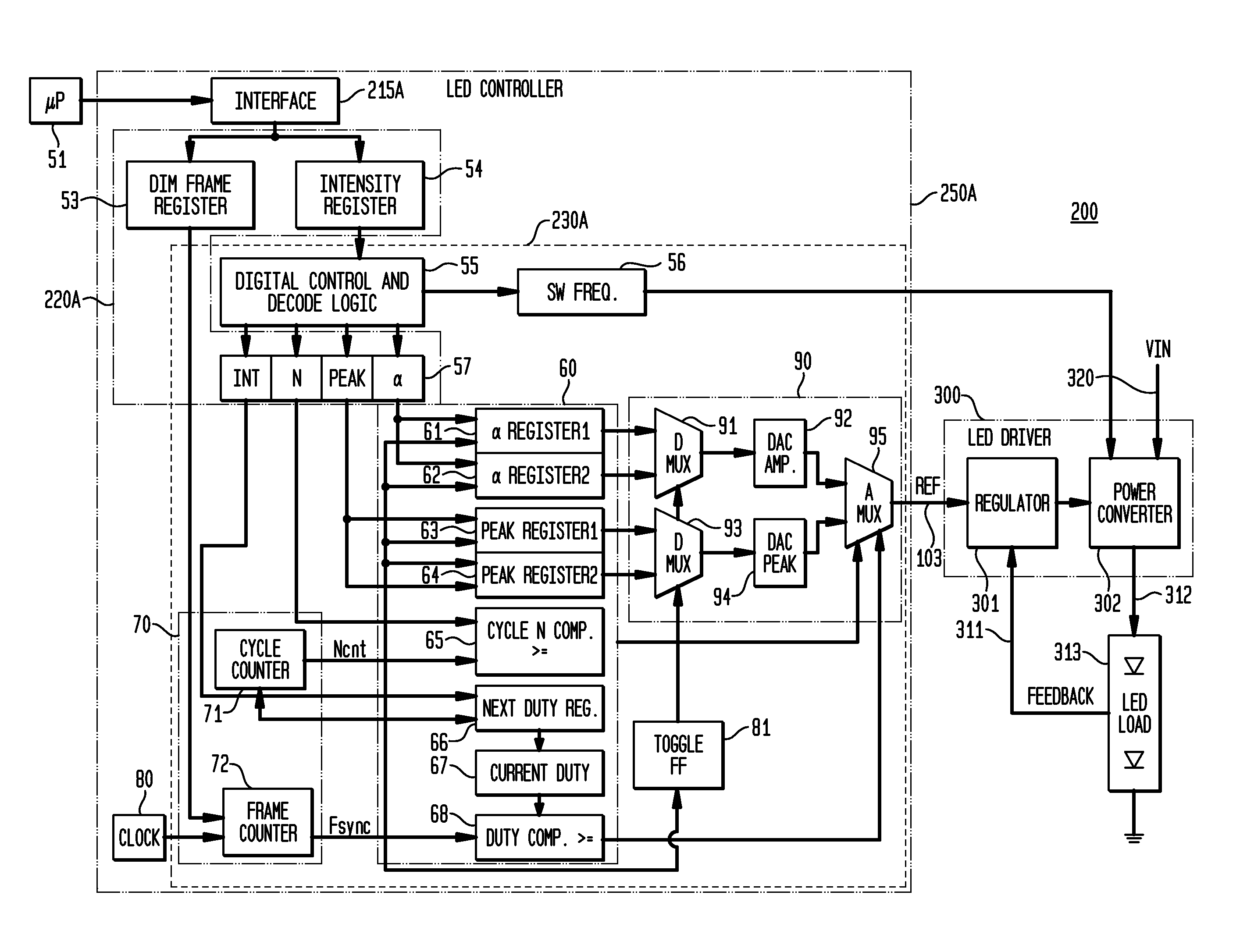
[0011]The exemplary embodiments of the present invention provide numerous advantages for controlling the intensity of light emissions for solid state devices such as LEDs, while simultaneously providing for substantial stability of perceived color emission, over both a range of intensities and also over a range of LED junction temperatures. The exemplary embodiments provide digital control, without requiring external compensation. The exemplary embodiments do not utilize significant resistive impedances in the current path to the LEDs, resulting in appreciably lower power losses and increased efficiency. The exemplary current regulator embodiments also utilize comparatively fewer components, providing reduced cost and size, while simultaneously increasing efficiency and enabling longer battery life when used in portable devices, for example.

Problems solved by technology

These prior art methods of controlling time averaged forward current of LEDs using different types of pulse modulations, at constant or variable frequency, by switching the LED current alternatively from a predetermined maximum value toward a lower value (including zero), creates electromagnetic interference (“EMI”) problems and also suffers from a limitation on the depth of intensity variation.
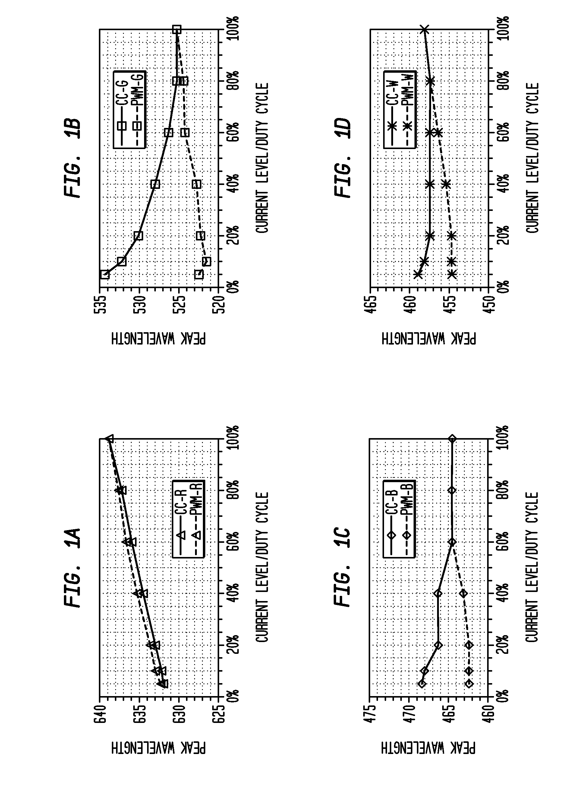
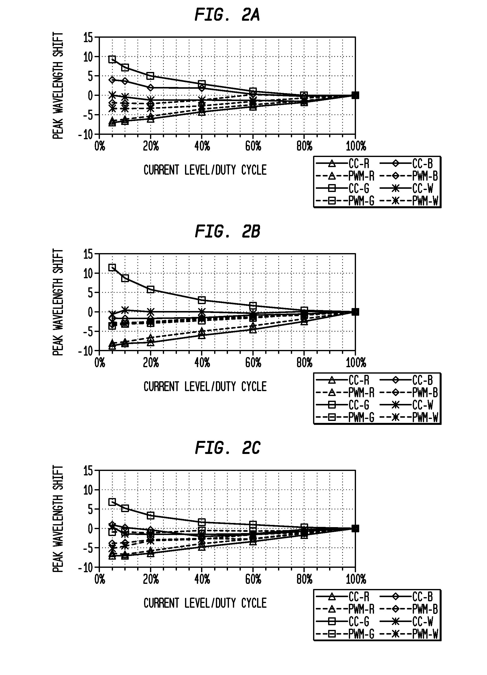
Analog control / Constant Current Reduction (or Regulation) (“CCR”), which typically varies the amplitude of the supplied current, also has various problems, including inaccurate control of intensity, especially at low current levels (at which component tolerances are most sensitive), and including instability of LED performance at low energy biasing of the p-n junction, leading to substantial wavelength shifting and corresponding color distortions.
As described in greater detail below with reference to FIGS. 1-3, both the PWM and CCR techniques of adjusting brightness also result in shifting the wavelength of the light emitted, further resulting in color distortions which may be unacceptable for many applications.
The various prior art methods of addressing such color distortions, which are perceptible to the human eye and which can interfere with desired lighting applications, have not been particularly successful.
Despite some improvement of intensity control and color mixing of these two patents, however, the proposed combinations of averaging techniques still do not address the resulting wavelength shifting and corresponding perceived color changes when these techniques are executed, either as a single analog control or as a combination of pulse and analog controls.

Method used


Image

  • Regulation of Wavelength Shift and Perceived Color of Solid State Lighting with Intensity and Temperature Variation
  • Regulation of Wavelength Shift and Perceived Color of Solid State Lighting with Intensity and Temperature Variation
  • Regulation of Wavelength Shift and Perceived Color of Solid State Lighting with Intensity and Temperature Variation

Examples


Embodiment Construction

[0092]While the present invention is susceptible of embodiment in many different forms, there are shown in the drawings and will be described herein in detail specific exemplary embodiments thereof, with the understanding that the present disclosure is to be considered as an exemplification of the principles of the invention and is not intended to limit the invention to the specific embodiments illustrated. In this respect, before explaining at least one embodiment consistent with the present invention in detail, it is to be understood that the invention is not limited in its application to the details of construction and to the arrangements of components set forth above and below, illustrated in the drawings, or as described in the examples. Methods and apparatuses consistent with the present invention are capable of other embodiments and of being practiced and carried out in various ways. Also, it is to be understood that the phraseology and terminology employed herein, as well as...


PUM


Abstract

Exemplary embodiments of the invention provide a system, apparatus, and method of controlling an intensity and spectrum of light emitted from a solid state lighting system. The solid state lighting has a first emitted spectrum at full intensity and at a selected temperature, with a first electrical biasing for the solid state lighting producing a first wavelength shift, and a second electrical biasing for the solid state lighting producing a second, opposing wavelength shift. Exemplary embodiments provide for receiving information designating a selected intensity level or a selected temperature; and providing a combined first electrical biasing and second electrical biasing to the solid state lighting to generate emitted light having the selected intensity level and having a second emitted spectrum within a predetermined variance of the first emitted spectrum over a predetermined range of temperatures.

Description

CROSS-REFERENCE TO A RELATED APPLICATION[0001]This application is a continuation-in-part of U.S. patent application Ser. No. 11 / 859,680, filed Sep. 21, 2007, inventors Dongsheng Zhou et al., entitled “Digital Driver Apparatus, Method and System for Solid State Lighting”, which is commonly assigned herewith, the contents of which are incorporated herein by reference, and with priority claimed for all commonly disclosed subject matter (the “related application”).FIELD OF THE INVENTION[0002]The present invention in general is related to power conversion, and more specifically, to a system, apparatus and method for supplying power to and controlling the wavelength of light emissions of solid state lighting devices, such as for controlling the intensity and wavelength of emissions from light emitting diodes utilized in lighting and other applications.BACKGROUND OF THE INVENTION[0003]Arrays of light emitting diodes (“LEDs”) are utilized for a wide variety of applications, including for ge...

Claims


Application Information

Patent Timeline
Patent Type & Authority Applications(United States)
IPC IPC(8): H05B41/36
CPCH05B33/0827H05B33/0866H05B33/0863H05B45/20H05B45/24H05B45/28H05B45/46
Inventor SHTEYNBERG, ANATOLYRODRIGUEZ, HARRYLEHMAN, BRADLEY M.ZHOU, DONGSHENG
Owner CHEMTRON RES
Why Eureka
Try Eureka